
Transmission structure of bionic manipulator finger and bionic manipulator

A technology of bionic machinery and transmission structure, applied in the field of grasping equipment, can solve the problems of small grasping force, low degree of freedom, and non-self-locking

Pending Publication Date: 2019-01-15
许志宏
View PDF0 Cites 4 Cited by
  • Summary
  • Abstract
  • Description
  • Claims
  • Application Information

AI Technical Summary

Problems solved by technology

The transmission structure of the bionic mechanical fingers in the prior art generally realizes the handling operation of grasping through the movement of the mechanical arm and the grasping of the robotic hand. The grasping method is carried out in an open way, and the grasping method is generally only by clamping the two sides of the workpiece, which cannot completely simulate the grasping operation of a real human hand. Due to structural problems, many designs in the past have small grasping force, and the powerless state Will loosen, not self-locking

Method used


Image

  • Transmission structure of bionic manipulator finger and bionic manipulator
  • Transmission structure of bionic manipulator finger and bionic manipulator
  • Transmission structure of bionic manipulator finger and bionic manipulator

Examples


Embodiment 1

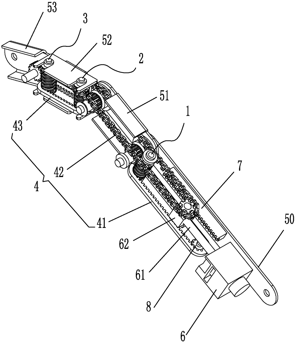
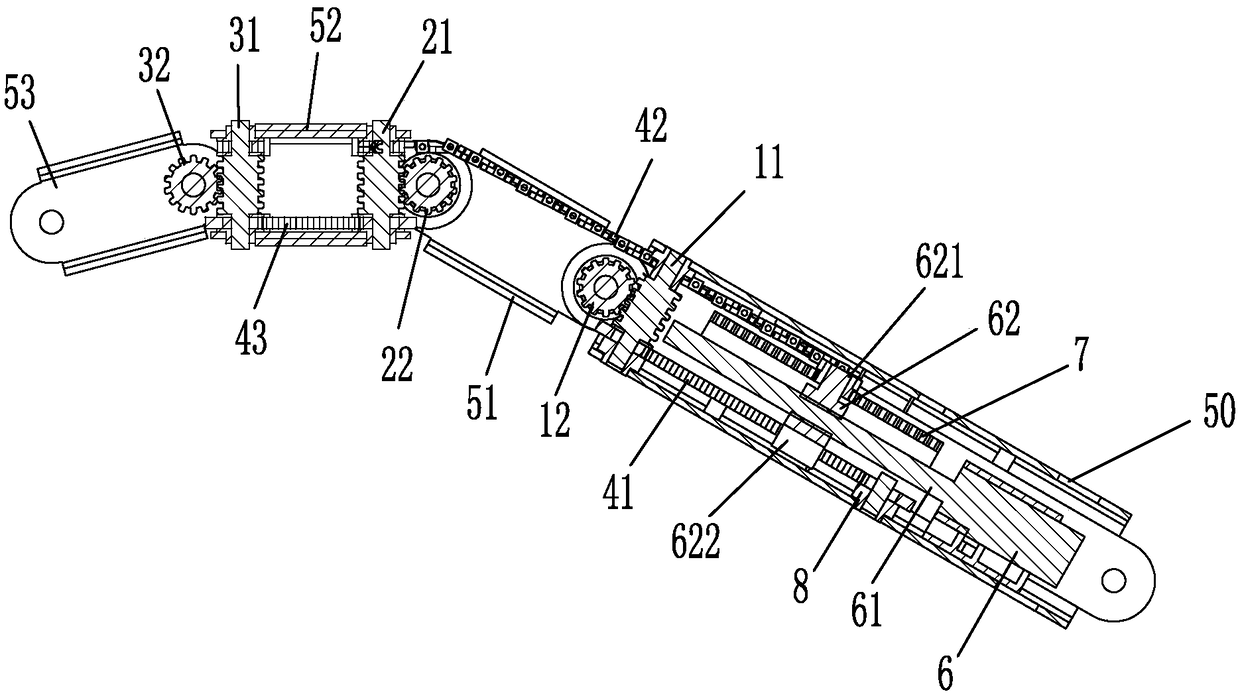
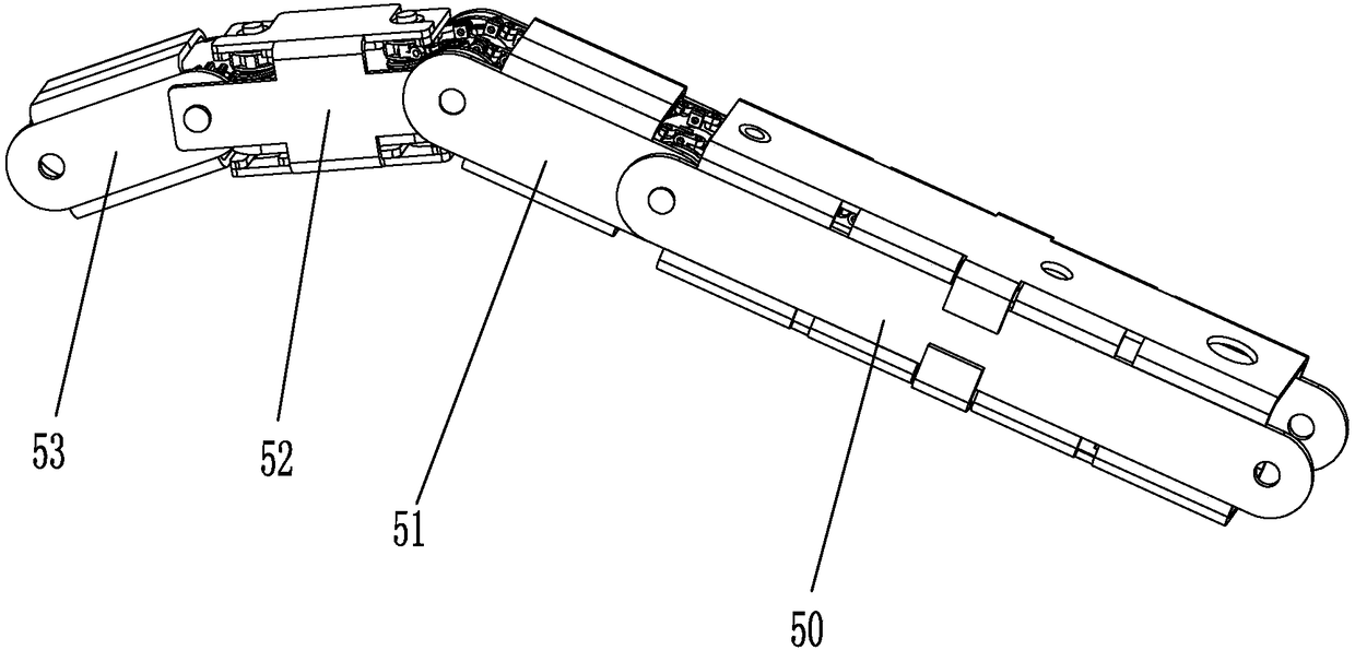
[0069] Such as Figure 1 to Figure 3 As shown, a transmission structure of a bionic mechanical finger, each joint in the transmission structure is provided with a group of worm gears driven by a chain belt as a joint movement mechanism; the transmission structure includes a finger outer frame, a transmission mechanism and adjustment unit;

[0070] The finger outer frame includes an adjustment unit outer frame 50, a first joint frame body 51, a second joint frame body 52 and a third joint frame body 53; the front end of the adjustment unit outer frame body 50 is located behind the first joint frame body 51 end and is hingedly connected with the rear end of the first joint frame body 51, and the front end of the first joint frame body 51 is located at the outside of the rear end of the second joint frame body 52 and is hingedly connected with the rear end of the second joint frame body 52 , the front end of the second joint frame body 52 is located outside the rear end of the t...

Embodiment 2

[0085] Such as Figure 14 As shown, a bionic manipulator includes a palm frame 54, five bionic mechanical fingers are installed on the palm frame 54, wherein four bionic mechanical fingers are transmission structures of the bionic mechanical fingers described in Embodiment 1; There is a bionic robotic finger for the thumb (see Figure 15 ), the thumb includes a thumb outer frame, a thumb transmission mechanism and a thumb adjustment unit;

[0086] The thumb outer frame includes an adjustment unit outer frame 50, a second joint frame body 52 and a third joint frame body 53;

[0087] The front end of the adjustment unit outer frame 50 is hingedly connected to the rear end of the second joint frame body 52, and the front end of the second joint frame body 52 is hingedly connected to the rear end of the third joint frame body 53; The front end of the frame body 53 is used as a free end;

[0088] The thumb adjustment unit includes a motor 6, a screw mandrel 61, a wire sleeve sli...


PUM


Abstract

The invention relates to the technical field of grabbing apparatuses, and particularly relates to a bionic manipulator. The bionic manipulator comprises a manipulator palm frame, and a plurality of manipulator fingers which are sequentially arranged on the palm frame, wherein each manipulator finger can be independently bent and stretched relative to the manipulator palm frame; an outer finger frame, a transmission mechanism and an adjusting unit form a transmission structure of each bionic manipulator finger; each transmission structure comprises three groups of worms and gears and three chain belts. The transmission structure is capable of performing multi-stage bending transmission, and each manipulator finger can be bent and stretch; the finger bearing capacity is improved relative toother designed bearing capacity based on the inter-gear transmission ratio, and moreover, the manipulator fingers can be automatically locked and cannot be loosened without power; a motor remains; andan existing state of the transmission structure remains.

Description

technical field [0001] The invention relates to the technical field of grasping instruments, in particular to a transmission structure of a bionic robot finger and a bionic robot hand. Background technique [0002] The bionic manipulator is an automatic operating device that can imitate certain movements and functions of the human hand and arm to grab, carry objects or operate tools according to a fixed program. It has the characteristics of saving manpower, good stability and high safety. The transmission structure of the bionic mechanical fingers in the prior art generally realizes the handling operation of grasping through the movement of the mechanical arm and the grasping of the robotic hand. The grasping method is carried out in an open way, and the grasping method is generally only by clamping the two sides of the workpiece, which cannot completely simulate the grasping operation of a real human hand. Due to structural problems, many designs in the past have small gra...

Claims


Application Information

Patent Timeline
Patent Type & Authority Applications(China)
IPC IPC(8): B25J9/10B25J15/00
CPCB25J9/104B25J15/0009
Inventor 许志宏
Owner 许志宏
Learn More