Connecting shaft driving device, sliding plug door driving device comprising connecting shaft driving device and sliding plug door comprising connecting shaft driving device

A technology of driving device and connecting shaft, which is applied to the suspension device of wing leaf, door/window accessories, power control mechanism, etc. It can solve the problems of unstable door closing or opening, potential safety hazards, door panel shaking, etc., so as to save power and reduce Damaged effect

Pending Publication Date: 2021-01-15
金湖县微晶控制系统有限公司
View PDF0 Cites 0 Cited by
  • Summary
  • Abstract
  • Description
  • Claims
  • Application Information

AI Technical Summary

Problems solved by technology

On the one hand, this kind of door lock structure has great potential safety hazards, because when the vehicle is driving, the road surface is bumpy and hollow, and the guide wheel on the door lock will roll back and forth in the guide groove, which will cause the door to be closed. Poor, when running at high speed, the airflow will enter the car from the door gap, affecting the passenger experience; when the vibration is large, the guide wheel may even slide out from the original path in the guide groove, which will cause the door to be broken. Automatic opening, there is a great security risk
On the other hand, in this door lock structure, the power source is fixed on the door frame, and the driving end of the power source is fixed on the guide wheel. When the door is closed or opened, the power applied by the power source is all applied to the guide wheel, and the guide wheel The wheel is the only point of force, and it is easy to cause the guide wheel to be damaged and accelerated due to stress concentration, and because there is only this point of force, when closing or opening the door, the door panels on both sides cannot be guaranteed to be absolutely synchronized, which will cause the two sides to close Or the absolute balance cannot be guaranteed when opening, which may easily cause the door panel to shake
[0004] In order to solve the above-mentioned potential safety hazards, the general solution is to add a cylinder or motor to pull the guide wheel after the door is closed, so that the guide wheel is limited in the guide groove, but this method needs to be used after the door is closed. The larger pulling force limits the position of the guide wheel; and the above-mentioned problem of instability when closing or opening the door has not been solved well, which does not conform to the concept of green environmental protection in today's society

Method used


Image

  • Connecting shaft driving device, sliding plug door driving device comprising connecting shaft driving device and sliding plug door comprising connecting shaft driving device
  • Connecting shaft driving device, sliding plug door driving device comprising connecting shaft driving device and sliding plug door comprising connecting shaft driving device
  • Connecting shaft driving device, sliding plug door driving device comprising connecting shaft driving device and sliding plug door comprising connecting shaft driving device

Examples


Embodiment approach 1

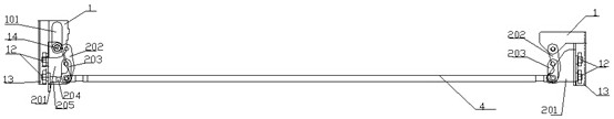
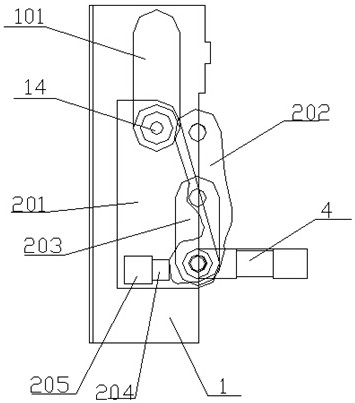
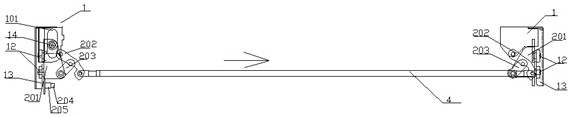
[0029] This embodiment provides a coupling drive device, such as Figures 1 to 6 As shown, it is mainly composed of a base 1 and two sets of shaft-connected drive mechanisms 2 . Two sets of shaft-connecting drive mechanisms 2 are respectively installed on both ends of the upper part of the base 1. The two sets of shaft-connecting drive mechanisms 2 are mainly composed of a sliding bracket 201, a driving arm 202 and a connecting arm 203. The driving arms in the two sets of connecting shaft driving mechanisms 2 One end of 202 is rotatably connected by pull rod 4 . At least one set of sliding brackets 201 in the shaft-connecting drive mechanism 2 is installed on the base 1 through a guide mechanism, and can reciprocate relative to the base 1 under the action of external force and the guide mechanism; the guide mechanism is a guide wheel or a guide block 14 , the guide wheel or guide block 14 is installed on the sliding bracket 201, and the guide wheel or guide block 14 is limite...

Embodiment approach 2

[0035] This embodiment is basically the same as Embodiment 1, the only difference is that when the coupling driving device in Embodiment 1 is applied to the sliding door, the driving cylinder is used to apply external force, while the coupling driving device in this embodiment is applied to When the sliding door is on, use the driving motor to apply external force (the driving motor is fixed on the pull rod, its output shaft is connected with a screw, and the screw nut on the screw is connected with the guide wheel of the sliding door).

[0036] The difference from Embodiment 1 is that when the drive motor is used to apply an external force, when the sliding bracket 201 moves down to the extreme position of the bracket guide groove 101 in a straight line along the bracket guide groove 101, the rotation connection point of the pull rod 4 and the driving arm 202, the driving The four points of the rotation connection point between the arm 202 and the base 1, the rotation connecti...


PUM


Abstract

The invention relates to the field of driving mechanisms, and discloses a connecting shaft driving device, a sliding plug door driving device comprising the connecting shaft driving device and a sliding plug door comprising the connecting shaft driving device. The connecting shaft driving device is characterized in that the two ends of a base are each provided with a connecting shaft driving mechanism, the two connecting shaft driving mechanisms are fixedly connected through a sliding rod and rotationally connected through a pull rod, the sliding rod is sleeved with two sliding sleeves, and the two ends of a drawn wire are connected with the two sliding sleeves after being wound around two wire drawing wheels correspondingly; a guide wheel rotationally connected to one sliding sleeve is limited in a guide groove in the base; a power source of the sliding plug door is fixed on the pull rod, and a driving end of the sliding plug door is fixedly connected with one of the sliding sleeves;and the connecting shaft driving mechanisms are driven by the power source to do reciprocating motion relative to the base. The connecting shaft driving device is applied to the sliding plug door, andforce originally concentrated on the guide wheel can be dispersed into the guide wheel and the connecting shaft driving mechanisms on the two sides of the guide wheel, so that the sliding plug door is very stable when opened or closed, the phenomenon that the guide wheel is automatically disengaged from the guide groove is effectively avoided, damage to the guide wheel can be greatly reduced, power is saved, and environment friendliness is achieved.

Description

technical field [0001] The invention relates to the field of driving mechanisms, in particular to a shaft-connected driving device, a sliding door driving device including the device, and a sliding door. Background technique [0002] At present, bus doors, subway doors or high-speed rail doors usually use sliding doors. The sliding door has good sealing performance and takes up less space, making the overall model beautiful and generous. The quality of the sliding door lock directly affects the quality of the sliding door. Security and sealing, in order to improve the security of sliding door, the researcher in the field mainly puts the object of research on the structure of sliding door lock. [0003] The currently used plug door lock structure is usually when the door is closed, a guide wheel on the door lock is introduced into the guide groove through a guide groove on the vehicle frame, and the movement of the door lock is restricted by this guide groove, and the door T...

Claims


Application Information

Patent Timeline
Patent Type & Authority Applications(China)
IPC IPC(8): E05F15/56E05F15/655E05F15/652E05D15/10
CPCE05D15/1007E05D2015/1026E05F15/56E05F15/565E05F15/652E05F15/655
Inventor 吕思华郑善友常超
Owner 金湖县微晶控制系统有限公司
Why Eureka
Try Eureka