Shank fracture fixing device for orthopedics department

A fixation device and calf technology, applied in fractures, non-surgical orthopedic operations, medical science, etc., can solve problems such as retention in plaster, patient wrestling, and changes in the center of gravity of the patient's body, so as to save manpower and avoid over-clamping effects

Pending Publication Date: 2022-07-08
张明英
View PDF1 Cites 0 Cited by
  • Summary
  • Abstract
  • Description
  • Claims
  • Application Information

AI Technical Summary

Problems solved by technology

[0002] After people fracture their calf, they need to stay in bed for a period of time to restore and heal the broken bone. The existing fracture care method mainly uses plaster fixation. In order to allow the blood circulation of the leg, the medical staff will keep the patient straight or exercise. The plaster has poor air permeability, so that the sweat produced by the calf will stay in the plaster during exercise and affect the recovery of the patient's calf. Therefore, it is necessary to design a fixation device
[0003] Patent application: CN210330864U, the publication date is 20200417, which discloses a fixation device for calf fracture care. By placing the support inner plate inside the leg support structure, the strength of the leg support structure is improved without affecting the leg support structure. Elasticity, put the foot and calf inside the leg support structure, fit the bottom of the foot with the pad, cover the leg fixing plate on the instep and the front of the calf, and then put the connecting strap through the leg connecting strap hole and the foot connecting strap hole Fix the leg fixing plate inside, and then inflate the inside of the airbag through the inflation port, so that the breathable layer fits the calf to improve the fixing effect, and open the leg outer plate air vent on the outside of the leg support structure, and set the pressure plate air vent on the outside of the leg fixing plate , the device fixes the calf through the leg support structure, but the device does not have a mechanism to support the center of gravity of the body during use, which may easily cause the patient's body center of gravity to change and cause wrestling
[0004] We designed an orthopedic leg fracture fixation device that is convenient for people to support, in order to overcome the effect that the existing fixation device does not support the body's center of gravity when it is used, and it is easy to cause the patient to fall

Method used


Image

  • Shank fracture fixing device for orthopedics department
  • Shank fracture fixing device for orthopedics department
  • Shank fracture fixing device for orthopedics department

Examples


Embodiment 1

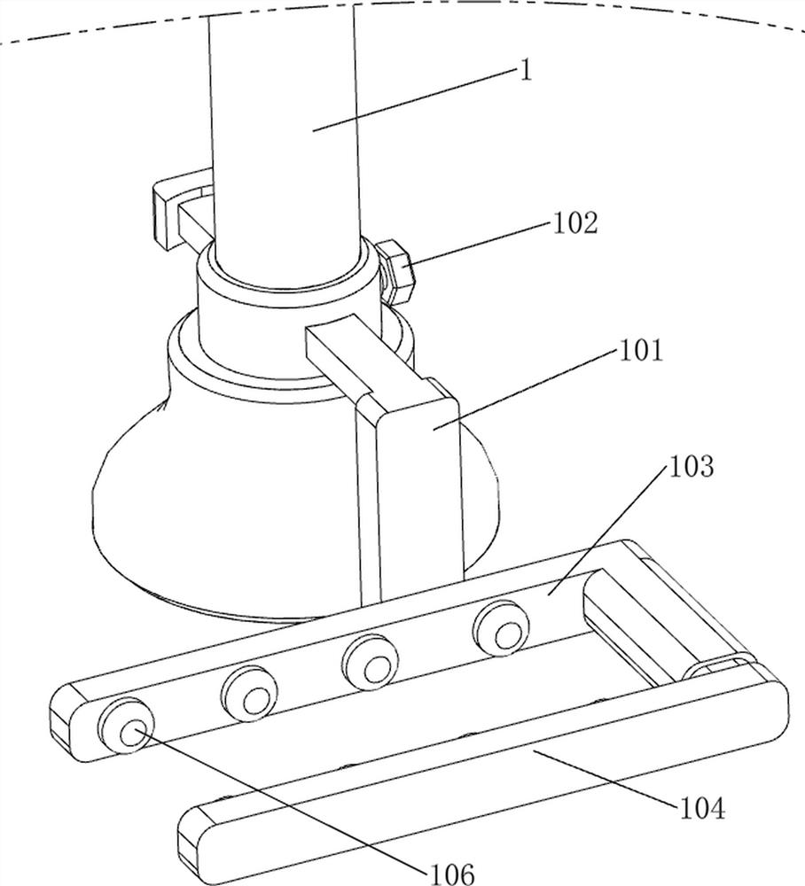
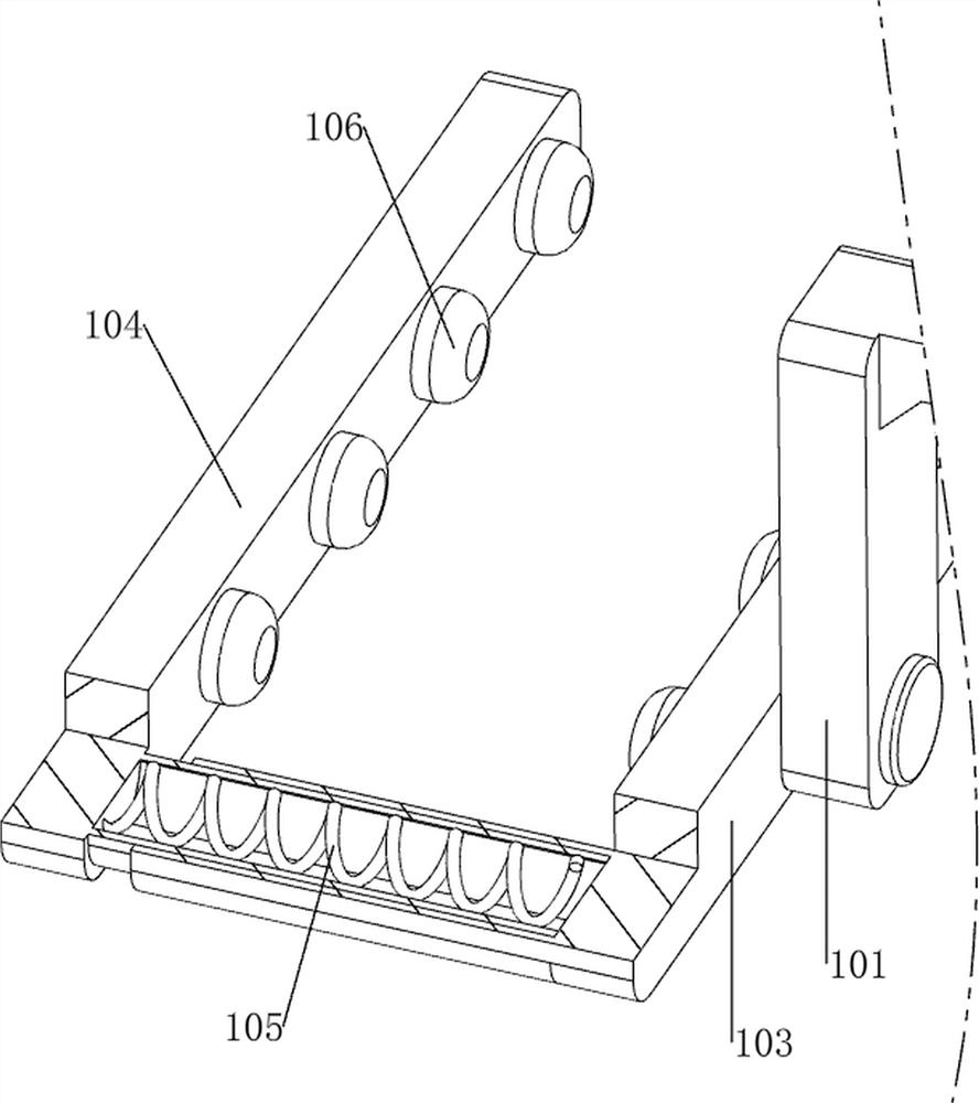
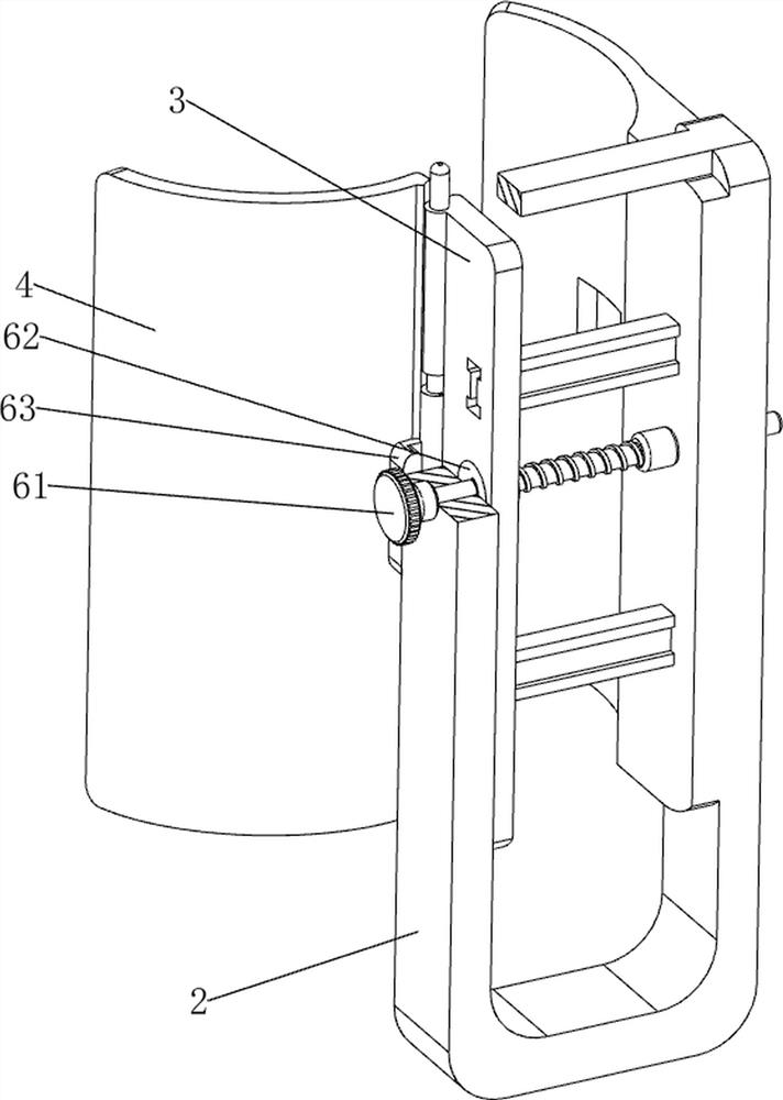
[0074] An orthopedic calf fracture fixation device, reference now figure 1 , including a crutch 1, a mounting frame 2, a first slider 3, a hinge plate 4, a positioning mechanism 5 and a fixing mechanism 6, the right side of the crutch 1 is provided with a positioning mechanism 5, and the positioning mechanism 5 is used to adjust the height of the hinge plate 4, positioning The mechanism 5 is provided with an installation frame 2, the installation frame 2 is slidably provided with a first sliding block 3, a through hole is opened on the first sliding block 3, and the front side of the first sliding block 3 is hingedly connected with a hinge plate 4, A fixing mechanism 6 is connected between the sliding block 3 , the mounting frame 2 and the hinge plate 4 .

[0075] Reference now Figure 1-3 The positioning mechanism 5 includes a first guide rod 51, a first guide sleeve 52, a second guide sleeve 53 and a first bolt 54. The right side of the crutch 1 is welded with a first guide...

Embodiment 2

[0079] On the basis of Example 1, now refer to figure 1 , Figure 7 and Figure 8 , also includes an overturning mechanism 7, the overturning mechanism 7 includes a spur gear 71, a spur gear 72 and a first torsion spring 73, the right lower side of the mounting frame 2 is fixed with a spur gear 71 by bolts, and the hinge plate 4 The lower side is rotatably provided with a spur gear 72 . The spur gear 72 meshes with the spur rack 71 . A first torsion spring 73 is connected between the spur gear 72 and the hinge plate 4 , and the first torsion spring 73 is wound on the hinge plate 4 .

[0080] Reference now figure 1 , Figure 9 , Figure 10 and Figure 11 , also includes a self-locking mechanism 8, the self-locking mechanism 8 includes a first installation sleeve 81, a movable block 82, a second spring 83, a connecting rod 84, a second installation sleeve 85, a second guide rod 86, a guide rail 87, a first Two sliders 88 , ratchet racks 89 , third spring 810 and ratchet ge...


PUM


Abstract

The invention relates to a fixing device, in particular to a shank fracture fixing device for the orthopedics department. The invention provides an orthopedic shank fracture fixing device convenient for people to support. A shank fracture fixing device for the orthopedics department comprises a walking stick, a positioning mechanism, a mounting frame, a first sliding block, a hinge plate, a fixing mechanism and the like. A positioning mechanism is arranged on the right side of the walking stick, a mounting frame is arranged on the positioning mechanism, a first sliding block is slidably arranged on the mounting frame, a hinged plate is hinged to the front side of the first sliding block, and a fixing mechanism is connected among the first sliding block, the mounting frame and the hinged plate. According to the walking stick, the shank is placed between the mounting frame and the hinged plate by people, then the screw rod is manually rotated by people, so that the shank is fixed by the hinged plate and the mounting frame, and after fixing, people hold the walking stick to walk, so that the supporting effect is achieved, and wrestling caused by the fact that the gravity center of the body is changed when people use the walking stick is avoided.

Description

technical field [0001] The invention relates to a fixation device, in particular to an orthopedic calf fracture fixation device. Background technique [0002] After a calf fracture, people need a period of bed rest to restore and heal the broken bone. The existing fracture care methods mainly use plaster fixation. In order to allow the blood circulation of the leg, the medical staff will keep the patient straight or exercise. The plaster has poor air permeability, so that the sweat produced by the calf will stay in the plaster during exercise and affect the recovery of the patient's calf. Therefore, a fixation device needs to be designed. [0003] Patent application: CN210330864U, published on 20200417, discloses a fixation device for calf fracture nursing. By placing a support inner plate inside the leg support structure, the strength of the leg support structure is improved, and the strength of the side plate of the leg support structure is not affected. Elasticity, place...

Claims


Application Information

Patent Timeline
Patent Type & Authority Applications(China)
IPC IPC(8): A61F5/058A61F5/052A61H3/02
CPCA61F5/0585A61H3/02A61H2003/007A61H2003/005A61H2205/106A61H2205/12
Inventor 张明英
Owner 张明英
Why Eureka
Try Eureka