Industrial fluid valve

An industrial and fluid technology, applied in the field of industrial fluid valves, can solve problems such as valve stem looseness, poor sealing effect, and fluid overflow

Pending Publication Date: 2021-07-30
胡银威
View PDF0 Cites 1 Cited by
  • Summary
  • Abstract
  • Description
  • Claims
  • Application Information

AI Technical Summary

Problems solved by technology

[0005] Aiming at the deficiencies of the prior art, the present invention provides an industrial fluid valve, which solves the problem that the structure of the traditional fluid valve is too simple, it cannot be self-locked during use, and the valve stem is prone to loosening, which is not conducive to the operation of the valve. The flow control and the sealing effect are poor at the same time. Under the action of the fluid pressure, the fluid is easy to overflow from the valve stem, and then leakage occurs, resulting in a waste of resources and reducing the use performance.

Method used


Image

  • Industrial fluid valve
  • Industrial fluid valve
  • Industrial fluid valve

Examples


Embodiment example 1

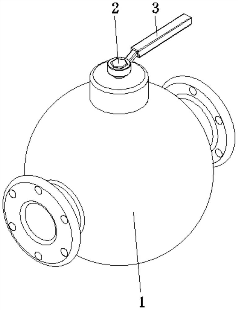
[0034] see Figure 1-8 , the present invention provides a technical solution: an industrial fluid valve, including a valve body 1, a valve stem 2, and a handle 3, the valve stem 2 is rotatably connected to the top center of the valve body 1, and the handle 3 is fixed on the valve stem 2 top;

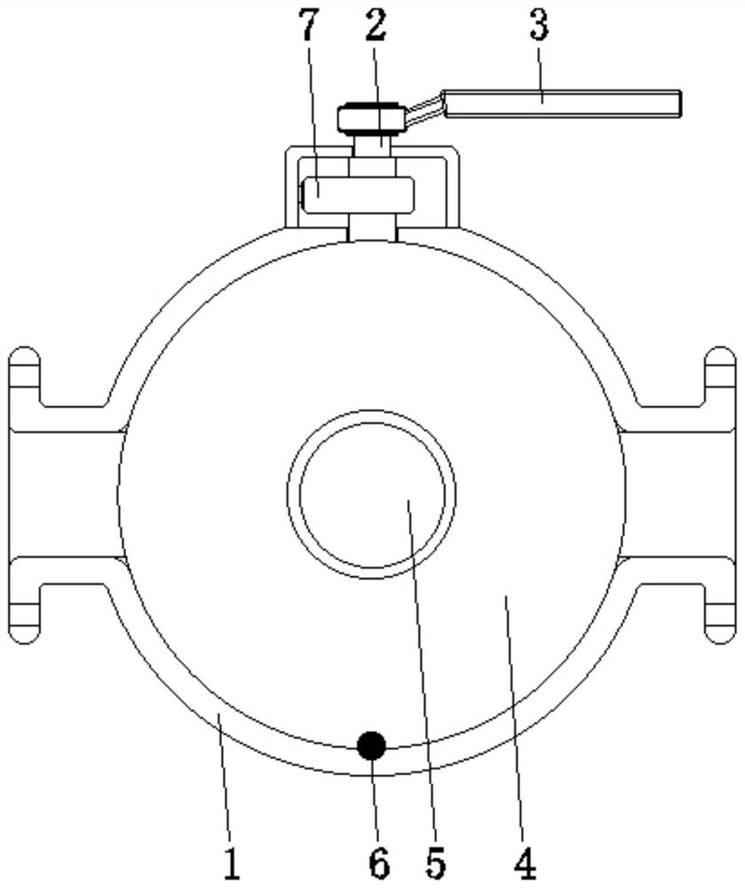
[0035] The inside of the valve body 1 is provided with a spool device 4, a through hole 5, a ball 6, and a clamping device 7. The spool device 4 is arranged inside the valve body 1 and is located at a central position. The bottom end of the valve stem 2 and the spool device The top of 4 is fixedly connected, the through hole 5 is set at the inner center of the valve core device 4, the ball 6 is set at the bottom center of the valve core device 4 and is connected with the bottom of the inner wall of the valve body 1, and the clamping device 7 is set on the valve body. The top of the body 1 is connected with the valve stem 2, and the valve stem 2 is clamped by the clamping device 7, so as...

Embodiment example 2

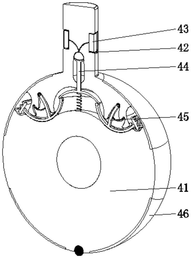
[0041] The clamping device 7 is provided with a connection block 71, an elastic caliper 72, and an arc protrusion 73. The surface side of the connection block 71 is fixedly connected with the top side of the valve body 1, and the elastic caliper 72 is fixed on the surface side of the connection block 71. , the arcuate protrusions 73 are fixed on the corresponding two sides of the inner wall of the elastic caliper 72. When the clamping device 7 is stuck on the surface of the valve stem 2, the elastic calipers 72 provide the clamping force, and the arcuate protrusions 73 and the limit concave The groove 42 cooperates to increase the contact area, avoid shaking, improve stability, and at the same time increase the contact area, so that the elastic air bag 43 outside the valve stem 2 is completely squeezed, which helps to be inside the valve stem 2 The elastic airbag 43 inflates rapidly, thereby increasing the driving force, helping to improve the sealing effect and reduce the leak...


PUM


Abstract

The invention discloses an industrial fluid valve. The industrial fluid valve comprises a valve body, a valve rod and a handle, the valve rod is rotationally connected to the center of the top of the valve body, the handle is fixed to the top of the valve rod, a valve element device, a through hole, a ball and a clamping device are arranged in the interior of the valve body, the valve element device is arranged in the interior of the valve body and located in the center, the bottom end of the valve rod is fixedly connected with the top of the valve element device, the through hole is formed in the center of the interior of the valve element device, the ball is arranged in the center of the bottom of the valve element device and connected with the bottom of the inner wall of the valve body in a matched mode, and the clamping device is arranged on the top of the valve body and connected with the valve rod in a matched mode. The invention relates to the technical field of general equipment manufacturing. According to the industrial fluid valve, the anti-loosening purpose is achieved, the valve rod can be clamped, then loosening can be effectively prevented, fluid control is facilitated, the sealing effect is good, the condition of leakage is reduced, and the use performance is improved.

Description

technical field [0001] The invention relates to the technical field of general equipment manufacturing, in particular to an industrial fluid valve. Background technique [0002] With the continuous development of valve technology and the continuous expansion of valve application fields, the corresponding valve standards are becoming more and more indispensable. Valve industry products have entered a period of innovation. A valve is a mechanical device that controls the flow, flow direction, pressure, temperature, etc. of a flowing fluid medium, and a valve is a basic component in a piping system. Valves are also divided into cast iron valves, cast steel valves, stainless steel valves, chrome molybdenum steel valves, chrome molybdenum vanadium steel valves, duplex steel valves, plastic valves, non-standard custom valves and other valve materials according to the material. Valves can be used to control the flow of various types of fluids such as air, water, steam, various co...

Claims


Application Information

Patent Timeline
Patent Type & Authority Applications(China)
IPC IPC(8): F16K1/226F16K1/32F16K1/36F16K31/60
CPCF16K1/2261F16K1/2266F16K1/32F16K1/36F16K31/60
Inventor 不公告发明人
Owner 胡银威
Why Eureka
Try Eureka