
Production technology of damping rubber ring and hydraulic forming device of damping rubber ring

A shock-absorbing rubber ring and production process technology, which is applied to other household appliances, household components, household appliances, etc., can solve the problems of increasing the labor intensity of the staff, affecting the efficiency of production, and affecting the progress of production, so as to reduce labor intensity , improve efficiency and prolong service life

Active Publication Date: 2019-01-15
ANHUI LONGCHUAN RUBBER & PLASTIC TECH CO LTD
View PDF8 Cites 2 Cited by
  • Summary
  • Abstract
  • Description
  • Claims
  • Application Information

AI Technical Summary

Problems solved by technology

[0002] The motor is one of the commonly used driving equipment. There are mostly flanges between the motor and the driven part. The flange acts as a bridge between the motor and the driven part and plays an important role in production. The flange directly affects the motor and the driven part. The coaxiality of the installation connection, if the coaxiality is not good, the vibration and noise are large, which directly affects the service life of the motor, driven parts and flanges during the work process, improves the maintenance rate of the equipment, and the driven parts cannot operate normally. , affecting the progress of production, most of the flanges in the prior art do not have shock-absorbing rubber rings. If the equipment requires high equipment, the shock-absorbing rubber rings added to the flanges are directly thermoformed with silica gel. Deformation, poor fatigue resistance, short service life, short replacement cycle, frequent replacement affects the progress of production, increases the labor intensity of the staff, and affects the efficiency of production

Method used


Image

  • Production technology of damping rubber ring and hydraulic forming device of damping rubber ring
  • Production technology of damping rubber ring and hydraulic forming device of damping rubber ring
  • Production technology of damping rubber ring and hydraulic forming device of damping rubber ring

Examples


Embodiment Construction

[0075] The following will clearly and completely describe the technical solutions in the embodiments of the present invention with reference to the accompanying drawings in the embodiments of the present invention. Obviously, the described embodiments are only some, not all, embodiments of the present invention. Based on the embodiments of the present invention, all other embodiments obtained by persons of ordinary skill in the art without creative efforts fall within the protection scope of the present invention.

[0076] In describing the present invention, it is to be understood that the terms "opening", "upper", "lower", "thickness", "top", "middle", "length", "inner", "surrounding" etc. Indicating orientation or positional relationship is only for the convenience of describing the present invention and simplifying the description, and does not indicate or imply that the components or elements referred to must have a specific orientation, be constructed and operated in a sp...


PUM

PropertyMeasurementUnit
thicknessaaaaaaaaaa
lengthaaaaaaaaaa
widthaaaaaaaaaa

Abstract

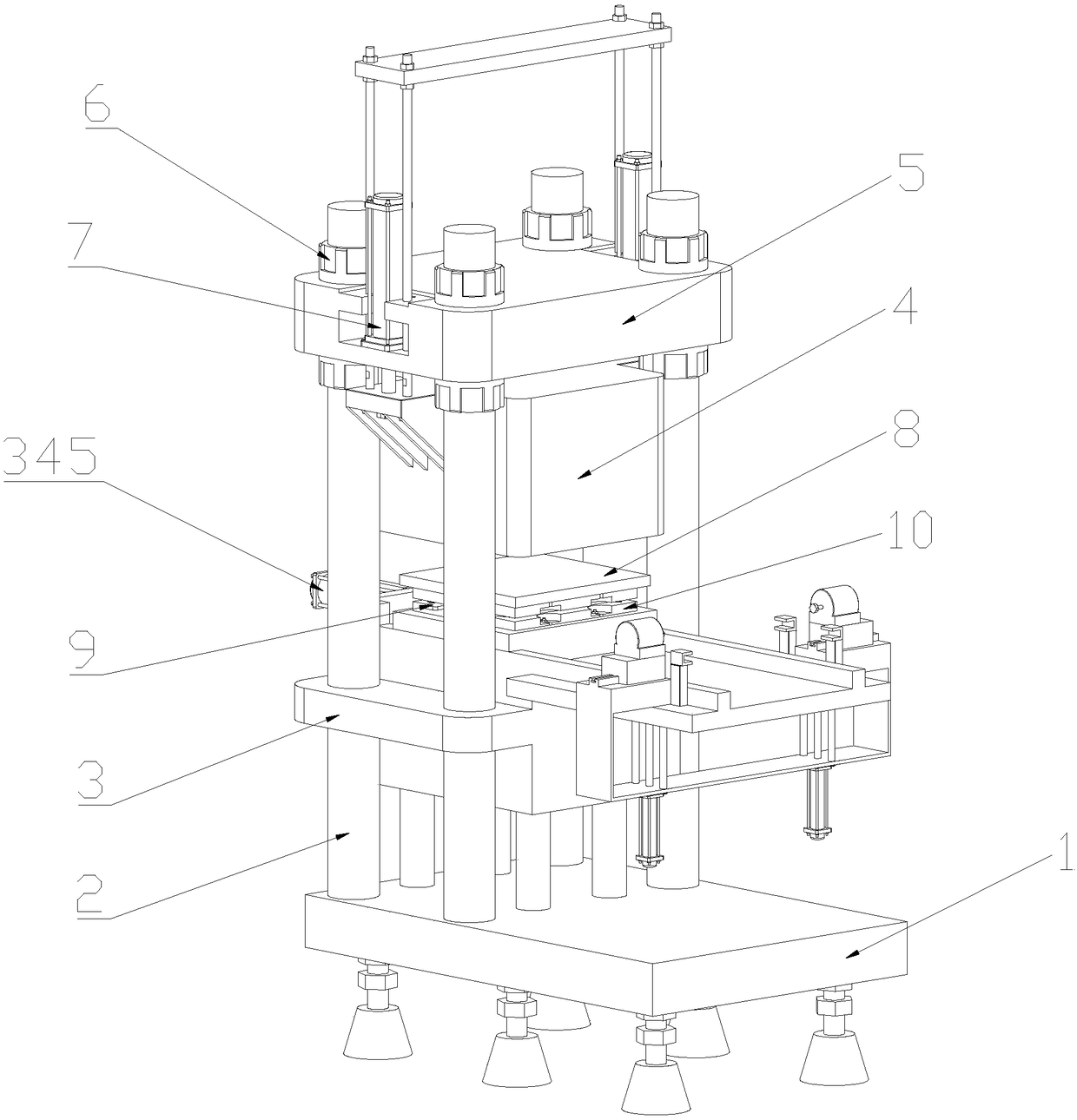
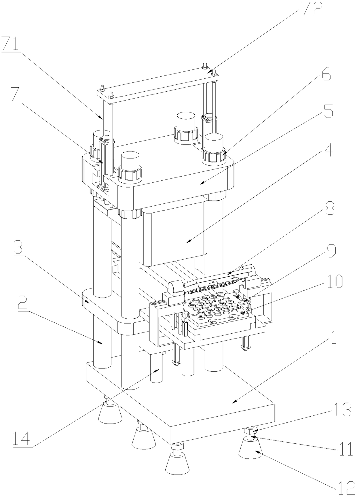
The invention discloses a hydraulic forming device of a damping rubber ring and a production technology of the damping rubber ring. The production technology of the damping rubber ring comprises the steps of manufacturing a steel ring, wherein material preprocessing and shearing are conducted, and a mold is rolled; preprocessing the steel ring, wherein the outer appearance of the steel ring is detected, passivation treatment is conducted on the steel ring, and sand blast is conducted on the inner ring of the steel ring; conducting spray coating on the inner ring of the steel ring, wherein a spray coating agent is prepared in the manner that absolute ethyl alcohol and Thinkbond4 are evenly mixed, the concentrate of the absolute ethyl alcohol in the prepared spray coating agent is larger than 99%, the water content is smaller than 0.1%, and spray coating treatment is conducted on the inner ring of the steel ring; and conducting combination by means of the vulcanization technology, wherein the hydraulic forming machine is utilized to conduct extrusion formation on silica gel and the steel ring. According to the damping rubber ring produced by the adoption of the production technology,on the basis of an original rubber ring, the steel ring is additionally arranged, so that the fatigue resistance of the damping rubber ring is improved, the service life is prolonged, the work efficiency is improved, and the labor intensity of work personnel is lowered; the steel ring is coated with the spray coating agent formed by evenly mixing the absolute ethyl alcohol and Thinkbond4, and therefore the efficiency of the vulcanization technology is improved; and the spray coating agent has ultrahigh adhesive force, and therefore the quality of the product is improved.

Description

technical field [0001] The invention relates to the technical field of motor shock-absorbing aprons, in particular to a production process of a shock-absorbing apron and hydraulic forming equipment thereof. Background technique [0002] The motor is one of the commonly used driving equipment. There are mostly flanges between the motor and the driven part. The flange acts as a bridge between the motor and the driven part and plays an important role in production. The flange directly affects the motor and the driven part. The coaxiality of the installation connection, if the coaxiality is not good, the vibration and noise are large, which directly affects the service life of the motor, driven parts and flanges during the work process, improves the maintenance rate of the equipment, and the driven parts cannot operate normally. , affect the progress of production. Most of the flanges in the prior art do not have damping rubber rings. If the equipment requires high equipment, th...

Claims


Application Information

Patent Timeline
Patent Type & Authority Applications(China)
IPC IPC(8): B29C43/18B29C43/32B29C43/36B29C35/02B21C37/00B23P15/00
CPCB21C37/00B23P15/00B29C35/02B29C43/18B29C43/32B29C43/36B29C2043/182B29C2043/185B29C2043/3602B29L2031/7096
Inventor 王银川王莹莹杨自祺
Owner ANHUI LONGCHUAN RUBBER & PLASTIC TECH CO LTD
Learn More