
A current receiver lifting shoe mechanism

A current collector and lifting shoe technology, which is applied in the field of rail transit, can solve the problems of potential safety hazards, inability to use under the train, long length, etc.

Active Publication Date: 2020-12-11
ZHUZHOU ELECTRIC LOCOMOTIVE CO LTD
View PDF9 Cites 1 Cited by
  • Summary
  • Abstract
  • Description
  • Claims
  • Application Information

AI Technical Summary

Problems solved by technology

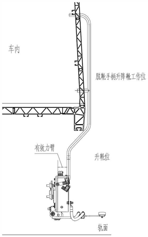
When lowering the boots on the car, the operator must stick his body out of the car body more before using the handle to lower the boots, which has potential safety hazards; the current design requires a long handle for lowering the boots on the car, which cannot be used under the car, so The long boot handle and the short boot handle need to be used separately to take off the boots under the car

Method used


Image

  • A current receiver lifting shoe mechanism
  • A current receiver lifting shoe mechanism
  • A current receiver lifting shoe mechanism

Examples


Embodiment

[0038] Such as Figure 4 and Figure 5 As shown, the current collector lifting shoe mechanism in this embodiment includes a long boot handle 1 and a short boot handle 2 hinged to the long boot handle 1, and the hinged end of the long boot handle 1 is fixed through the shaft hole interference fit. There is a limiter 3, and the hinged end of the short boot handle 2 is fitted with a hinge 4 through the threaded shaft hole. The limiter 3 is provided with a hinge groove 31 on the side facing the hinge 4, and the end of the hinge 4 extends into the In the hinged groove 31 and hinged with the stopper 3, the hinged groove 31 is provided with an avoidance space for the hinged part 4 to swing around the hinge point; thus making the long boots-off handle 1 and the short boots-off handle 2 both in the long boots-off handle Rotate around the hinge point in the plane formed by the centerline of 1 and the centerline of short boot handle 2.

[0039] Such as Figure 6 As shown, the upper pa...


PUM


Abstract

A lifting boot mechanism of a current collector includes a long boot handle and a short boot handle hinged to the long boot handle, wherein the long boot handle and the short boot handle are both rotatable about a hinge point in a plane formed by a centerline of the long boot handle and a centerline of the short boot handle to push and pull the current collector to contact or disconnect the carbonslider of the current collector from the third rail. The long boot handle and the short boot handle are rotatable in a plane formed by a centerline of the long boot handle and a centerline of the short boot handle. Compared with the existing boot-removing handle, the mechanism adopts the joint-type handle structure, which increases the effective force arm when the boot-removing, so that the operator can save more labor. The mechanism can realize the operation of lifting boots or lowering boots by the operator in the whole process, and avoid the operator from protruding out of the vehicle to carry out the operation, thereby greatly improving the operation safety. The mechanism cleverly takes the short shoe-off handle as the part of the long shoe-off handle, which can reduce the storage space. When the mechanism is to be dismounted when the boot is manually lifted, only the short boot handle is operated.

Description

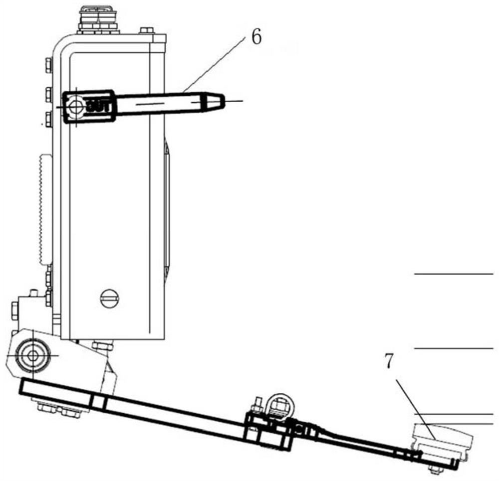
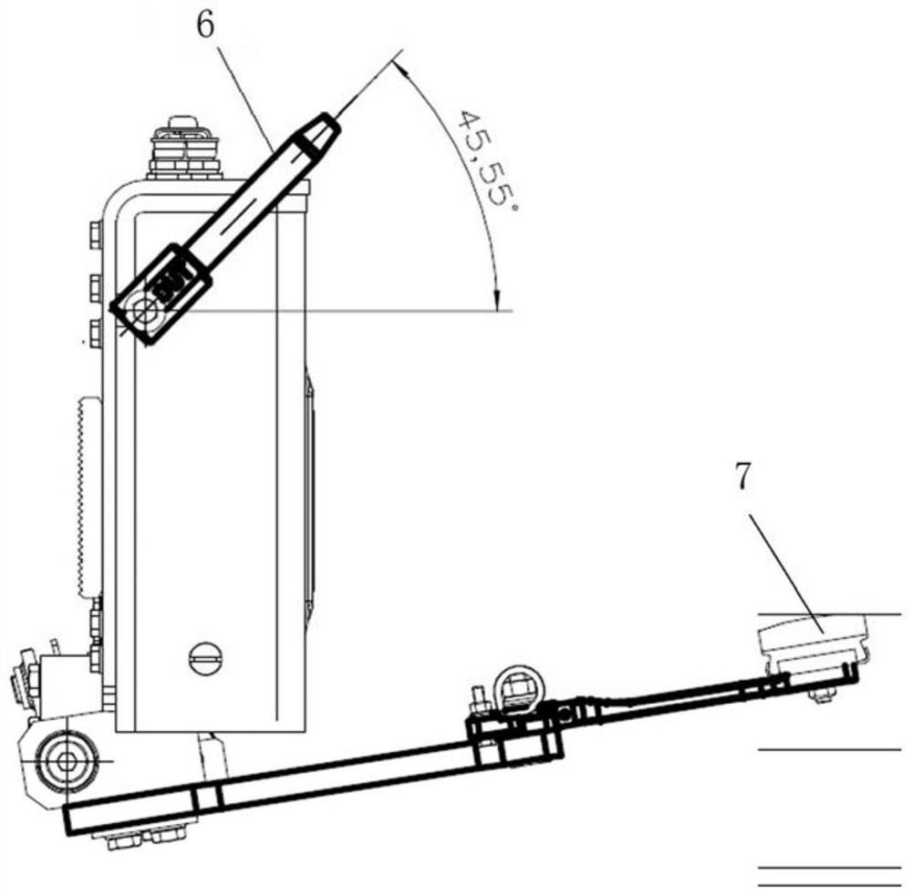
technical field [0001] The invention relates to the technical field of rail transit, in particular to a collector lifting shoe mechanism. Background technique [0002] The current collector, also known as the current collector shoe, is installed on the side frame of the bogie of the vehicle. During the operation of the train, the carbon slider is contacted with the third rail by the force of the spring to obtain electric energy, and the electric energy is provided to the train through the cable. Realize the power supply of the whole train. Such as figure 1 and figure 2 As shown, by controlling the rotation of the transmission rod 6 of the current collector, the contact or disconnection between the carbon slider and the third rail 7 can be controlled, so as to realize shoe lowering or shoe raising. [0003] The current collectors currently used in the market can be divided into manual and pneumatic according to the driving mode of the lifting shoe. The lowering shoe of t...

Claims


Application Information

Patent Timeline
Patent Type & Authority Patents(China)
IPC IPC(8): B60L5/39
CPCB60L5/39
Inventor 周洁张彦林陈珍宝林平陈明国张海丰尹正乾彭宝林李军冯叶王秋红孙宁梁坤
Owner ZHUZHOU ELECTRIC LOCOMOTIVE CO LTD
Learn More