
Vertical lifting device in construction

A vertical lifting and construction technology, applied in the direction of lifting device, lifting frame, etc., can solve the problems of increasing the physical labor of construction personnel, causing danger to construction personnel, and failing to achieve lifting accuracy, so as to facilitate material handling, improve safety, Reduce the effect of physical labor

Pending Publication Date: 2022-06-28
SHANDONG DAHAN CONSTR MACHINERY
View PDF20 Cites 0 Cited by
  • Summary
  • Abstract
  • Description
  • Claims
  • Application Information

AI Technical Summary

Problems solved by technology

[0003] With the continuous development of the construction industry, the technology of building construction is also constantly innovating. In the process of building construction, it is often necessary to transport building materials to high platforms. Various building materials need to be transported to On the platform, the vertical lifting transport devices currently on the market for building construction require construction workers to lean out and bend over to carry materials after lifting heavy objects during use, which easily puts construction workers in danger and causes Construction accidents. At the same time, during the transportation process, the physical labor of the construction personnel is increased, which brings inconvenience to the construction. In the lifting project, most of the ground operators perform visual operations, which easily fails to achieve the lifting accuracy, which in turn affects the transfer of materials.

Method used


Image

  • Vertical lifting device in construction
  • Vertical lifting device in construction
  • Vertical lifting device in construction

Examples


Embodiment

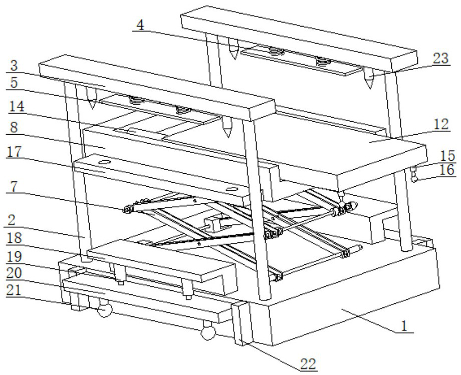
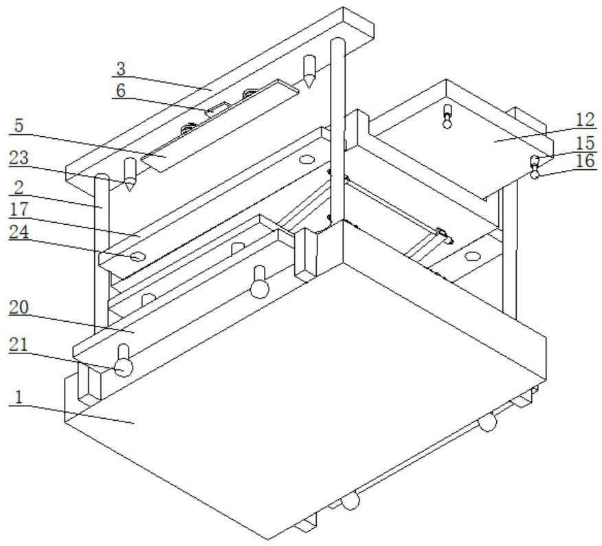
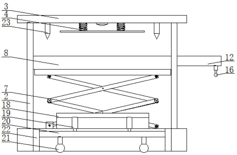
[0030] When using the device, first move the device to the use position, then place the material on the sliding plate 12, then the scissor lift mechanism 7 works, the scissor lift mechanism 7 drives the placing plate 8 to move upward, and the placing plate 8 moves to drive the connection The plate 17 moves upward with the material, the connecting plate 17 moves upward and contacts the pressure plate 5, the connecting plate 17 contacts the pressure plate 5 and drives the pressure plate 5 to move upward, the spring 4 is compressed, and the pressure plate 5 drives the elastic contact piece to contact the travel switch 6, and the shear The fork lift mechanism 7 stops working, then the first telescopic rod 14 works, the first telescopic rod 14 stretches and drives the connecting block 13 to move toward the direction of the construction worker, the connecting block 13 moves to drive the sliding plate 12 to move, and the sliding plate 12 moves to drive the roller 16 When moving, the r...


PUM


Abstract

The invention provides a vertical lifting device in construction, and mainly relates to the field of vertical lifting equipment. A vertical lifting device in construction comprises a bottom plate, vertical rods are installed at the four corners of the top face of the bottom plate, the top ends of the two vertical rods located on the front side of the bottom plate are connected through a transverse plate, the top ends of the two vertical rods located on the rear side of the bottom plate are connected through a transverse plate, and a pressing plate is installed on the bottom face of each transverse plate through a spring. The construction equipment has the beneficial effects that through cooperation of the first telescopic rod, the sliding plate and the rolling wheels, materials on the sliding plate can be moved to the side of a constructor, the constructor can carry the materials conveniently, the constructor is prevented from stretching out of the body to carry the materials, the safety guarantee of the constructor is improved, the physical labor of the constructor is reduced, and the construction efficiency is improved. And meanwhile, through cooperation of a travel switch and a contact elastic piece, the travel of the shear fork lifting mechanism can be controlled, then the material conveying precision is improved, constructors can conveniently carry materials, and convenience is brought to construction.

Description

technical field [0001] The invention mainly relates to the field of vertical lifting equipment, in particular to a vertical lifting device in construction. Background technique [0002] Building construction refers to the production activities in the implementation stage of project construction. It is the construction process of various buildings. It can also be said that the various lines on the design drawings are turned into real objects at the designated location. Main structure construction, roofing engineering construction, decoration engineering construction and high-rise building construction. [0003] With the continuous development of the construction industry, the technology of building construction is also constantly innovating. During the construction process, building materials often need to be transported to high platforms, and various building materials need to be transported to the On the platform, the vertical lifting and transportation devices currently o...

Claims


Application Information

Patent Timeline
IPC IPC(8): B66F7/06B66F7/28
CPCB66F7/065B66F7/0666B66F7/0625B66F7/28
Inventor 徐美徐兴华卢博霖李向辉温涛王保旭索传宗陈宾法谭涛鹿文东
Owner SHANDONG DAHAN CONSTR MACHINERY
Learn More