Silicon wafer loading equipment and loading method thereof

A technology for loading equipment and silicon wafers, which is applied in the field of silicon wafers, can solve the problems of small application range and unstable adsorption of silicon wafers, and achieve the effects of firm adsorption, stable placement of silicon wafers, and enlarged adjustment range

Active Publication Date: 2019-01-15
张家港市欧微自动化研发有限公司
View PDF6 Cites 0 Cited by
  • Summary
  • Abstract
  • Description
  • Claims
  • Application Information

AI Technical Summary

Problems solved by technology

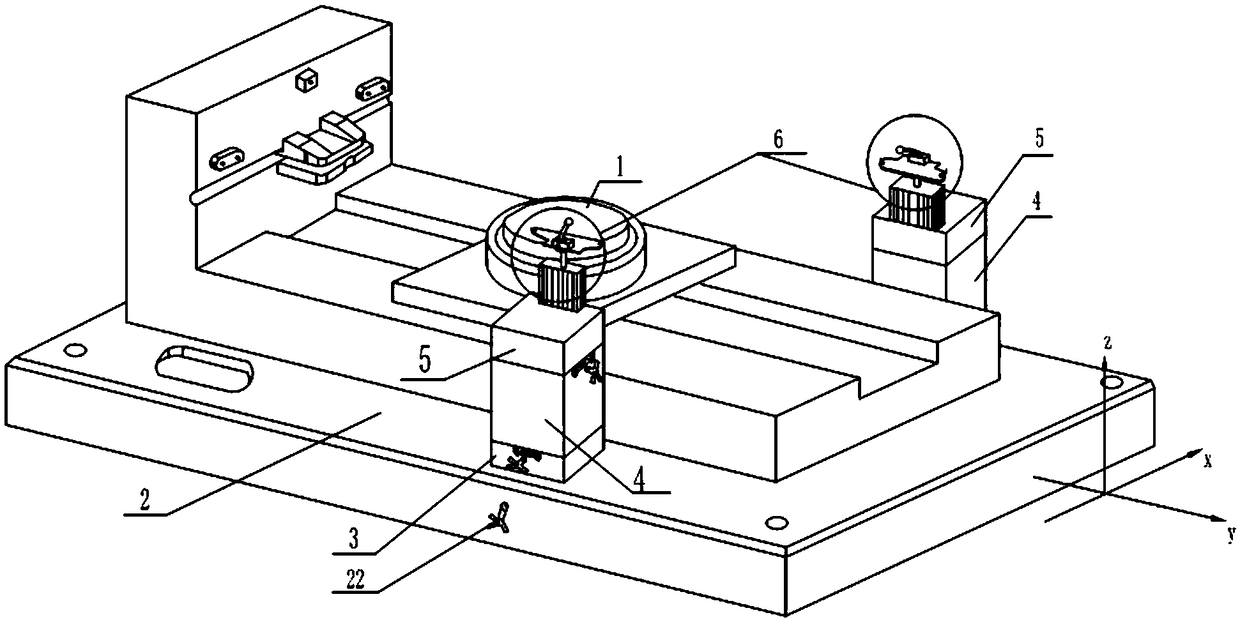
[0004] One of the technical problems of the object of the present invention is that the buffer loading device for silicon wafers in the prior art has a small application range and unstable adsorption of silicon wafers. A silicon wafer loading device is provided, which is suitable for silicon wafers of various sizes and expands its application range, and the silicon wafer is firmly adsorbed

Method used


Image

  • Silicon wafer loading equipment and loading method thereof
  • Silicon wafer loading equipment and loading method thereof
  • Silicon wafer loading equipment and loading method thereof

Examples


Embodiment Construction

[0059] In order to make the object, technical solution and advantages of the present invention clearer, the embodiments of the present invention will be further described in detail below in conjunction with the embodiments. It should be understood that the specific embodiments described here are only used to explain the embodiments of the present invention, and are not intended to limit the embodiments of the present invention.

[0060] In the description of the present invention, it should be noted that the terms "center", "upper", "lower", "left", "right", "vertical", "horizontal", "inner", "outer" etc. The indicated orientation or positional relationship is based on the orientation or positional relationship shown in the drawings, and is only for the convenience of describing the present invention and simplifying the description, rather than indicating or implying that the referred device or element must have a specific orientation, or in a specific orientation. constructio...


PUM


Abstract

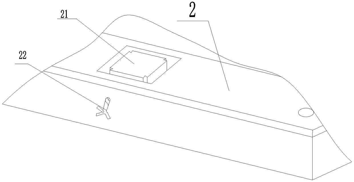
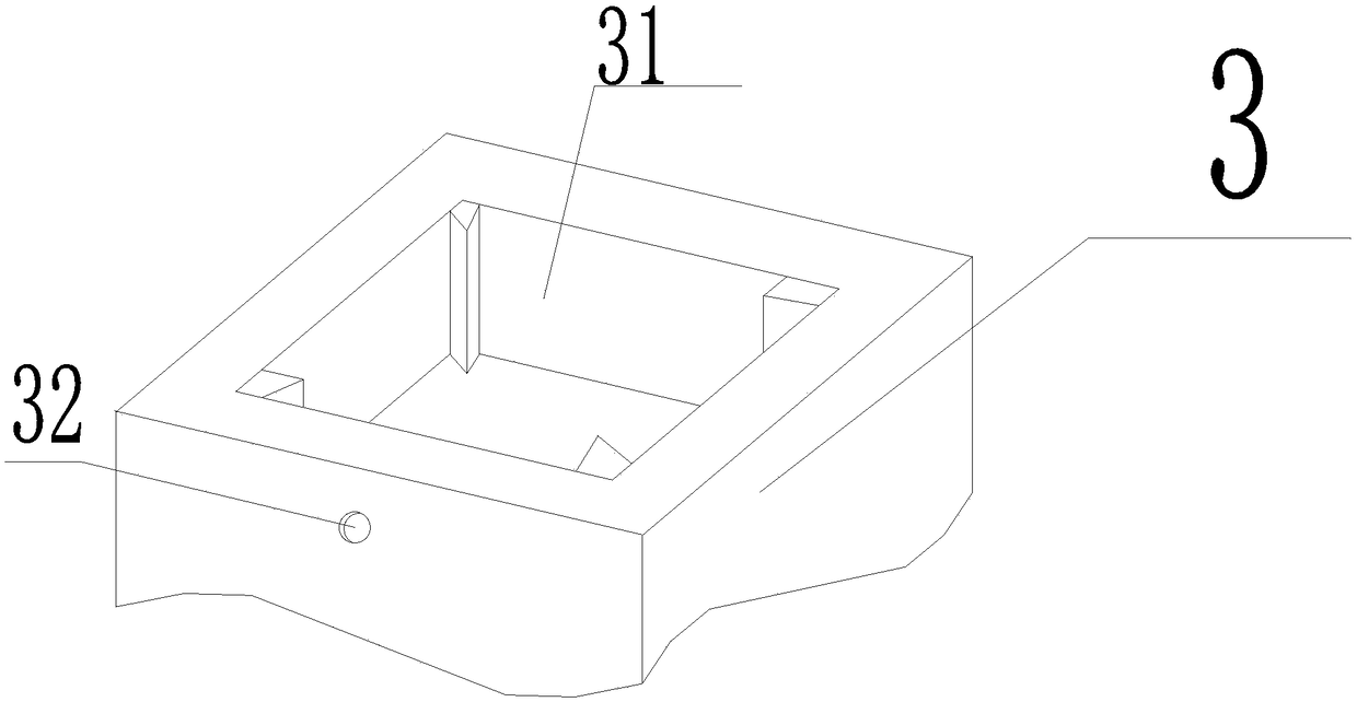
The invention discloses silicon wafer loading equipment. The silicon wafer loading equipment comprises a suction disc and a silicon wafer table, wherein the suction disc is located in the y direction;and the silicon wafer table is located below the suction disc and matched with the suction disc. The silicon wafer table is provided with a base, two first block bodies, two second block bodies and two third block bodies and two loading assemblies. The two first block bodies are located above the base; the connection line of the two first block bodies is parallel with the x direction; and the twofirst block bodies are located in the x negative direction. The two second block bodies are located above the first block bodies correspondingly and are in the x negative direction. The two third block bodies are located above the two second block bodies correspondingly and are in the x negative direction. The two loading assemblies are located above the third block bodies correspondingly and aresymmetrical about the y direction. The equipment can move in all directions and is applicable to silicon wafer samples of various sizes and large in application scope; and the silicon wafer samples can be adsorbed firmly.

Description

technical field [0001] The invention relates to the field of silicon wafers, in particular to a silicon wafer loading device and a loading method thereof. Background technique [0002] Chips are modern miniature "knowledge bases" with super-storage capabilities. The size, thickness, surface damage, and shape defects of the silicon wafer will have a huge impact on the performance of the silicon wafer, so it is necessary to perform fine measurement of the surface information of the silicon wafer. In the prior art, the optical measuring equipment used for measuring the surface information of silicon wafers loads silicon wafers through a silicon wafer buffer loading device during use. [0003] For example, the patent document CN201210479223.1 is a silicon wafer buffer loading device, including a silicon wafer table and a suction cup, the suction cup is matched with the silicon wafer table, the silicon wafer table has a base, and it is characterized in that it also includes a bu...

Claims


Application Information

Patent Timeline
Patent Type & Authority Applications(China)
IPC IPC(8): B65G47/90
CPCB65G47/901
Inventor 陈志忠
Owner 张家港市欧微自动化研发有限公司
Why Eureka
Try Eureka