Asymmetric filter tunnel structure of grain catcher

A particle filter and pore structure technology, applied in dispersed particle filtration, membrane filter, gas treatment and other directions, can solve problems such as affecting the performance of diesel engines, shortening the service life of the particle filter, increasing the regeneration frequency and increasing the cost of post-processing.

Active Publication Date: 2019-01-15
DALIAN UNIV OF TECH
View PDF11 Cites 4 Cited by
  • Summary
  • Abstract
  • Description
  • Claims
  • Application Information

AI Technical Summary

Problems solved by technology

[0002] The particulate filter is currently the most effective and widely used after-treatment device for particulate matter emissions. As the particulate matter is trapped on the wall of the tunnel, the exhaust back pressure will become higher and higher, which will affect the performance of the diesel engine. Therefore, it is necessary to periodically filter the particulate matter However, excessive regeneration frequency will not only increase the cost of aftertreatment, but also shorten the service life of the particle filter
Reducing the pressure drop increase rate of the particle filter has always been the focus of research at home and abroad. The traditional symmetrical wall-flow filter pore structure has the same shape and size as the inlet and outlet pores. The pressure drop increase rate is reduced by increasing the number of pores, but There is an upper limit to increase the number of meshes, and the manufacturing cost is too high

Method used


Image

  • Asymmetric filter tunnel structure of grain catcher
  • Asymmetric filter tunnel structure of grain catcher
  • Asymmetric filter tunnel structure of grain catcher

Examples


Embodiment 1

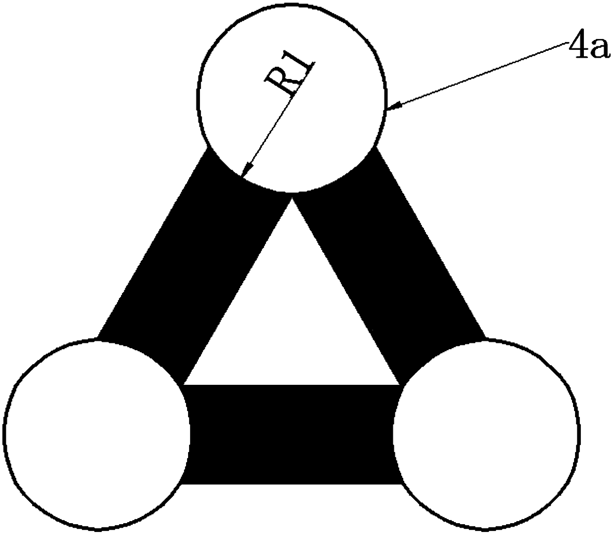
[0038] Such as Figure 3-5As shown, the hexagonal channel wall 4 and the triangular channel wall 5 are replaced by the curved channel wall 4a. The hexagonal channel wall 4 and the triangular channel wall 5 can be replaced separately or at the same time. The radii R1 and R2 of the curved channel wall 4a can be adjusted.

Embodiment 2

[0040] Such as Figure 6-8 As shown, the hexagonal channel wall 4 and the triangular channel wall 5 are replaced by the curved channel wall 4b. The hexagonal channel wall 4 and the triangular channel wall 5 can be replaced separately or at the same time. The angles A1 and A2 of the zigzag channel wall 4b can be adjusted.

[0041] It is also possible to replace the sides of the hexagonal channel with outwardly convex broken lines, and the sides of the triangular channel with outwardly convex curves. Or replace the sides of the hexagonal channels with outwardly convex curves, and replace the sides of the triangular channels with outwardly convex broken lines. The above embodiment adopts the convex curved channel wall 4a and the broken line channel wall 4b to further expand the volume of the inlet channel, increase the area of ​​the filter wall, and effectively improve the performance of the particle filter with an asymmetric channel structure.

[0042] The asymmetric pore stru...


PUM


Abstract

The invention provides an asymmetric filter tunnel structure of a grain catcher. A tunnel cross section of the asymmetric tunnel structure includes a combination of hexagon, square and triangle, hexagonal and triangular tunnels serve as inlet tunnels, a square tunnel serves as an outlet tunnel, and thus, the asymmetric tunnel structure in which the shape or area of the inlet tunnels is inconsistent with that of the outlet tunnel is formed. According to the structure, the volume of the inlet tunnel and the area of the filtering wall can be increased effectively, and compared with a traditionalsymmetric filter tunnel structure, both the volume of the inlet tunnel and the filtering area are increased by 30% respectively, and a grain filtering layer formed in the wall is thinner when grains in same number are caught. According to a calculation result, the extreme carbon carrying amount of the novel tunnel structure is increased by more than30%, and the structure has significance in reducing the regeneration frequency and prolonging the service life of the catcher.

Description

technical field [0001] The invention relates to the technical field of exhaust gas treatment of internal combustion engines, in particular to an asymmetric pore structure of a particle trap filter body. Background technique [0002] Particulate filter is currently the most effective and widely used after-treatment device for particulate matter emission. As particulate matter is trapped on the wall of the tunnel, the exhaust back pressure will become higher and higher, which will affect the performance of the diesel engine. Therefore, it is necessary to regularly filter particulate matter. However, excessive regeneration frequency will not only increase the cost of aftertreatment, but also shorten the service life of the particle filter. Reducing the pressure drop increase rate of the particle filter has always been the focus of research at home and abroad. The traditional symmetrical wall-flow filter pore structure has the same shape and size as the inlet and outlet channels...

Claims


Application Information

Patent Timeline
Patent Type & Authority Applications(China)
IPC IPC(8): F01N3/023
CPCF01N3/023B01D46/247B01D46/2488B01D46/249B01D46/2492B01D46/2486B01D46/2482F01N2330/06F01N2330/34F01N3/0222Y02T10/12B01D2279/30F01N3/022
Inventor 肖鸽隆武强田华
Owner DALIAN UNIV OF TECH
Why Eureka
Try Eureka