Indoor intelligent humidifying robot

A robotic and intelligent technology, applied in the field of robotics, can solve problems such as excessive humidification, foaming and falling off the wall surface, and affecting the service life of desks and other objects, so as to improve comfort and save water.

Inactive Publication Date: 2019-01-15
GUANGDONG HONGHUIJING TECH SERVICE CO LTD
View PDF6 Cites 5 Cited by
  • Summary
  • Abstract
  • Description
  • Claims
  • Application Information

AI Technical Summary

Problems solved by technology

[0003] Most of the existing humidification devices are started and shut down by manual control, which is prone to excessive humidification and excessive indoor air humidity, which affects people's normal work. At the same time, excessive indoor air humidity can easily cause the surface of the wall to bubble and fall off. , affecting the service life of objects such as desks

Method used


Image

  • Indoor intelligent humidifying robot
  • Indoor intelligent humidifying robot
  • Indoor intelligent humidifying robot

Examples


Embodiment 1

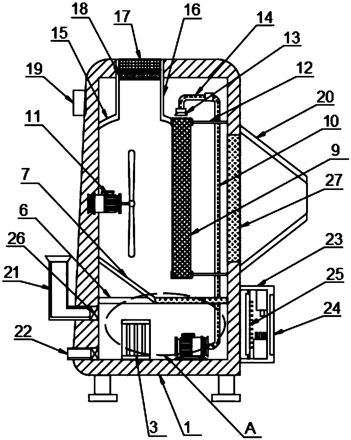
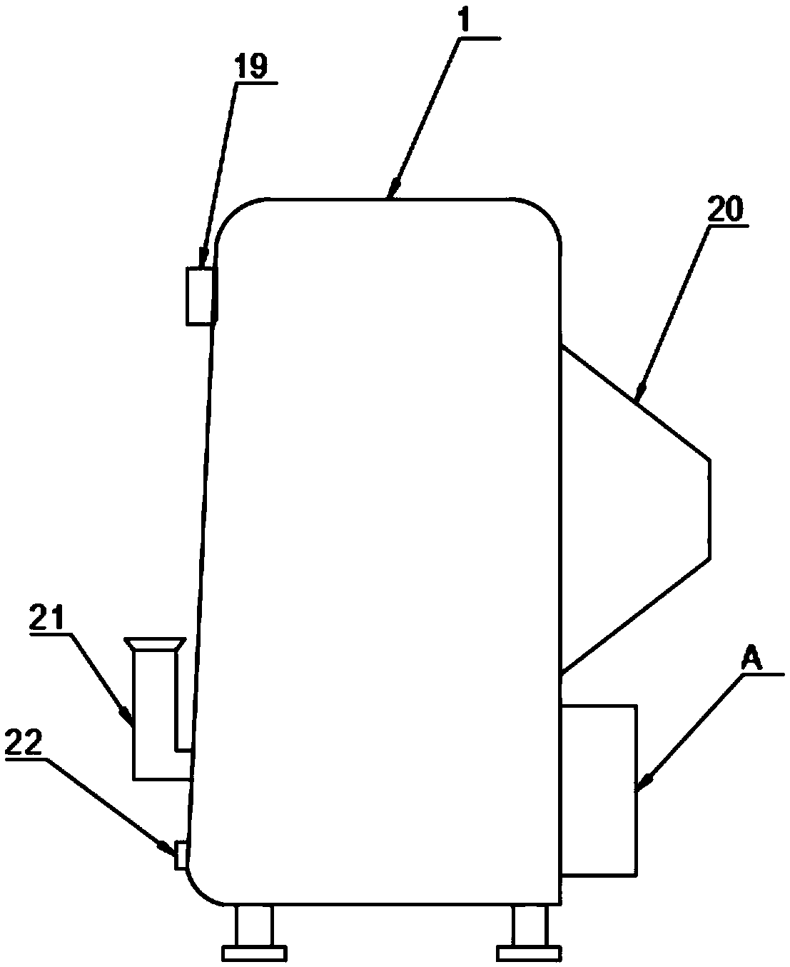
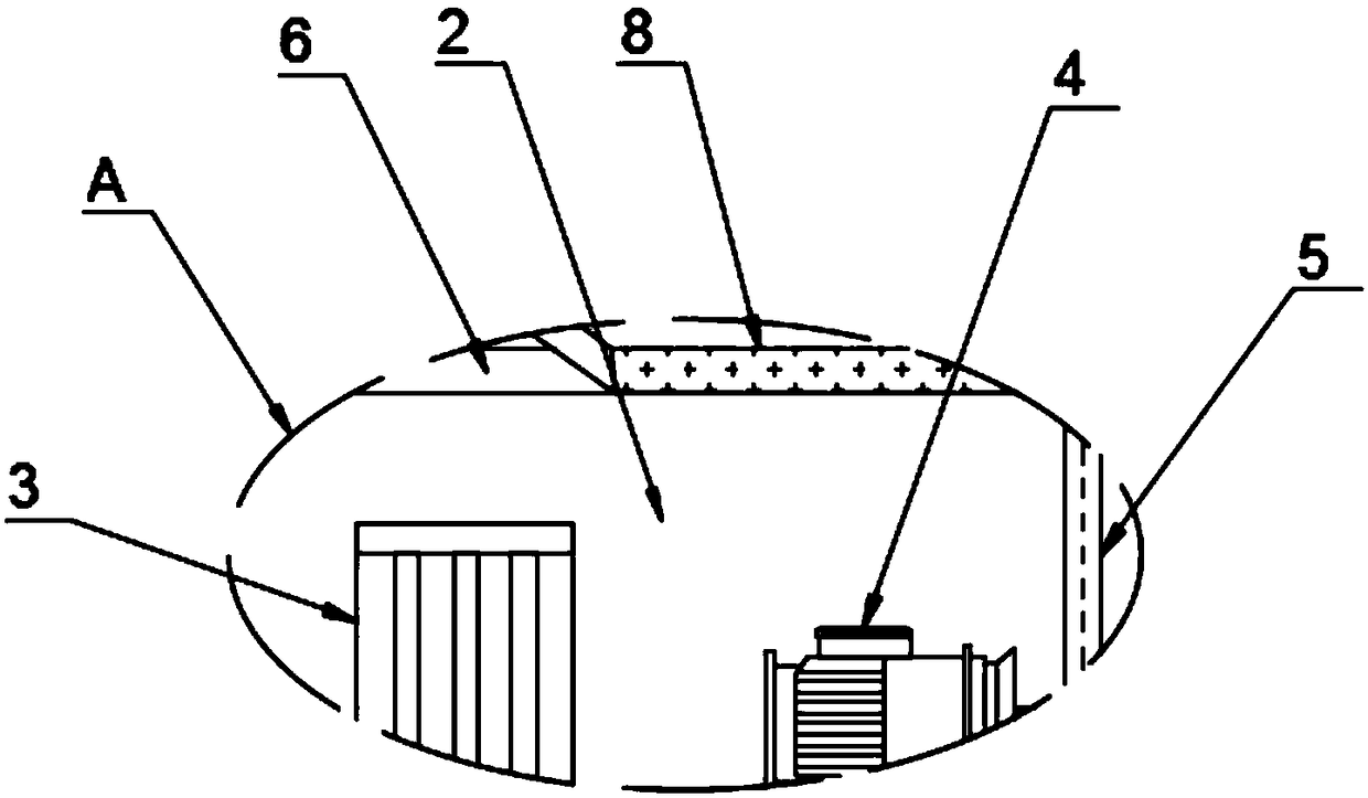
[0025] Such as Figure 1-4 The shown indoor intelligent humidification robot includes a housing 1, a water storage tank 2 is provided at the bottom of the inner cavity of the housing 1, and a heating pipe 3 is provided in the inner cavity of the water storage tank 2, and one side of the heating pipe 3 A pressure pump 4 is provided. The pressure pump 4 is provided with a transmission pipe 5. The water storage tank 2 includes a top plate 6, a drainage plate 7 is provided on the top of the top plate 6 and a filter screen 8 is provided at the bottom of the drainage plate 7 , The top of the water storage tank 2 is provided with a wet membrane module 9, one side of the wet membrane module 9 is provided with a connecting pipe 10 and the other side is provided with a fan 11, the side wall of the wet membrane module 9 is connected with a fixed rod 12 The top of the wet membrane module 9 is provided with a water distributor 13, the top of the water distributor 13 is provided with a three...

Embodiment 2

[0029] Such as Figure 1-4 In the shown indoor intelligent humidification robot, the ends of the water inlet pipe 21 and the water outlet pipe 22 both penetrate through the housing 1 and extend to the inside of the water storage tank 2. The ends of the water inlet pipe 21 and the water outlet pipe 22 are both provided with An electromagnetic valve 26, the input end of the electromagnetic valve 26 is connected to the output end of the central processing unit 25.

[0030] The transmission pipe 5 penetrates the water storage tank 2 and extends to the top of the water storage tank 2, the transmission pipe 5 and the connecting pipe 10 are integrally arranged, the top of the connecting pipe 10 is connected with the three-way pipe 14, and the filter screen 8 It is integrated with the top plate 6, the filter 8 is arranged directly below the wet membrane module 9, the fan 11 is fixedly connected to the inner wall of the housing 1, and the side wall of the housing 1 is provided with an air...


PUM


Abstract

The invention discloses an indoor intelligent humidifying robot which comprises a shell. A water storage tank is arranged at the bottom of the inner chamber of the shell, and a heating pipe is arranged in the inner chamber of the water storage tank. A pressure pump is arranged on one side of the heating pipe, and a transfer pipe is arranged on the pressure pump. The water storage tank comprises atop plate, a drainage plate is arranged at the top of the top plate, and a filter screen is arranged at the bottom of the drainage plate. A wet film component is arranged at the top of the water storage tank, a connecting pipe is arranged on one side of the wet film component, and a fan is arranged on the other side of the wet film component. The side wall of the wet film component is connected with a fixed rod. According the indoor intelligent humidifying robot, a way of intelligent control is adopted, and the information of indoor air is collected by a temperature and humidity sensor; the indoor intelligent humidifying robot is basically controlled by a central processor, a frequency converter is controlled to regulate the working frequency of the pressure pump and the fan so as to regulate and control the amount of moisture discharged by an air outlet pipe to adapt to the corresponding working environment, and excessive humidity in a working area is avoided.

Description

Technical field [0001] The invention relates to the field of robots, in particular to a robot for indoor intelligent humidification. Background technique [0002] A humidifier is a household appliance that increases the humidity in a room. With the development of the economy and the improvement of people's living standards, people have higher and higher requirements for the quality of life and health. In this way, air humidifiers have slowly entered many homes around the world, and have become an indispensable small household appliance for families in dry areas. Increasing the research and development of air humidifiers will benefit the development of the domestic air humidifier industry, as well as the improvement of national quality of life and the improvement of national health. In order to meet the needs of people for its use and aesthetic functions, air humidifiers have more refined product types, richer shapes, more delicate materials, and more eye-catching colors. [0003...

Claims


Application Information

Patent Timeline
Patent Type & Authority Applications(China)
IPC IPC(8): F24F6/04F24F3/16F24F11/52F24F11/70F24F11/77F24F13/00F24F13/28F24F110/10F24F110/20
CPCF24F6/04F24F13/00F24F13/28F24F2006/046F24F2221/34F24F11/52F24F11/70F24F11/77F24F2110/10F24F2110/20F24F8/10F24F8/158F24F8/20Y02B30/70
Inventor 陈杰
Owner GUANGDONG HONGHUIJING TECH SERVICE CO LTD
Why Eureka
Try Eureka