
Concrete rebound instrument based on annular spring

A ring-shaped spring and concrete technology, applied in instruments, scientific instruments, testing material hardness, etc., can solve the problems of unfavorable realization, inconvenient operation, large size of external auxiliary facilities, etc. Effect

Active Publication Date: 2019-01-15
WUHAN UNIV
View PDF12 Cites 0 Cited by
  • Summary
  • Abstract
  • Description
  • Claims
  • Application Information

AI Technical Summary

Problems solved by technology

However, the existing concrete rebound tester is held by the operator, and the external force is manually applied, and the type of activation after the spring stores energy has many inconveniences.
[0003] Most of the existing patents on concrete rebound hammer are based on the premise of not changing the spring energy storage structure of the rebound hammer, supplemented by external support facilities to improve the accuracy and operability of the measurement, but such measures have not improved Unstable factors during rebound, and the external auxiliary facilities are often too large in size, which is not conducive to the realization of inconvenient operation

Method used


Image

  • Concrete rebound instrument based on annular spring
  • Concrete rebound instrument based on annular spring
  • Concrete rebound instrument based on annular spring

Examples


Embodiment Construction

[0019] Below in conjunction with accompanying drawing and specific embodiment the present invention will be described in further detail:

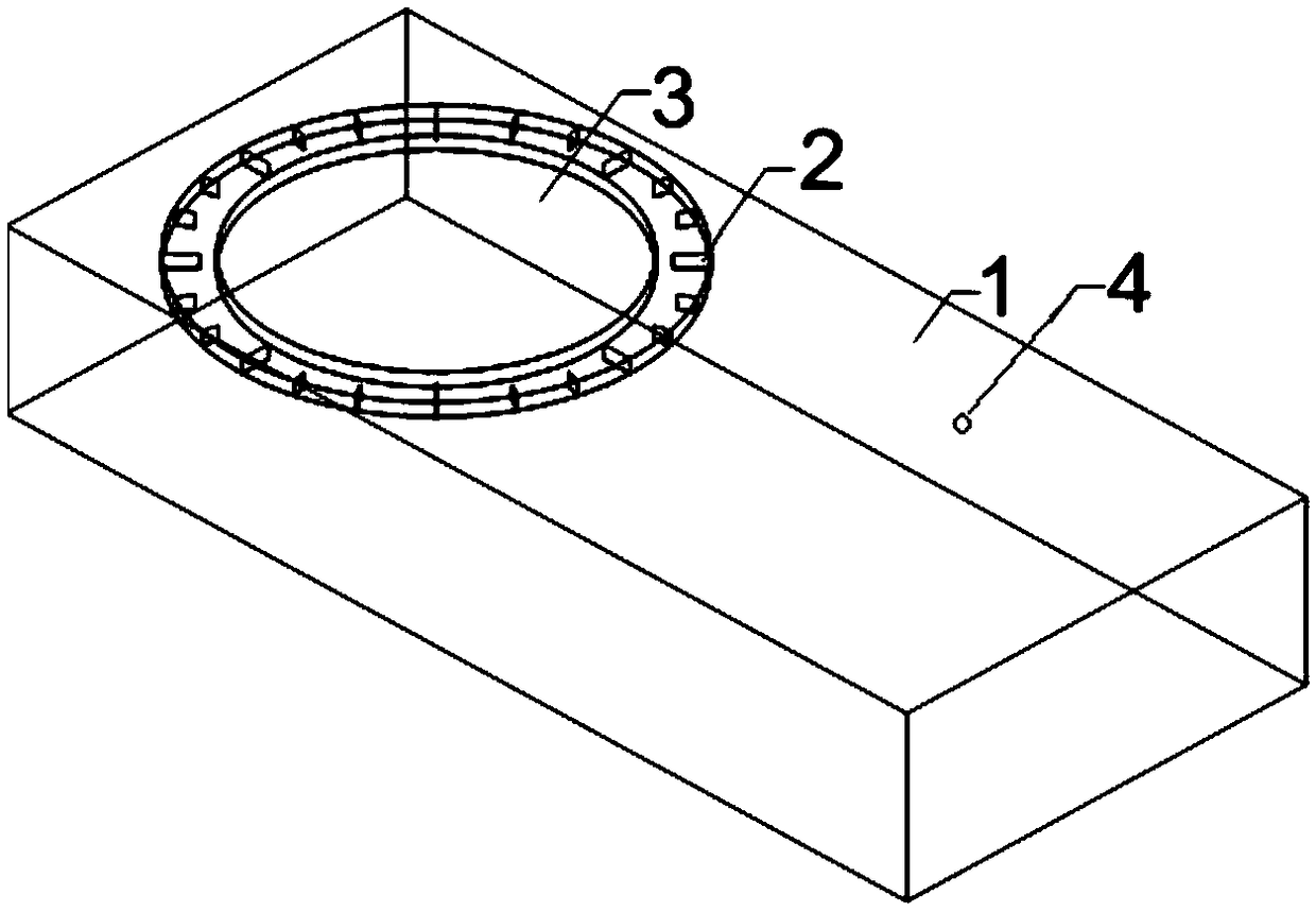
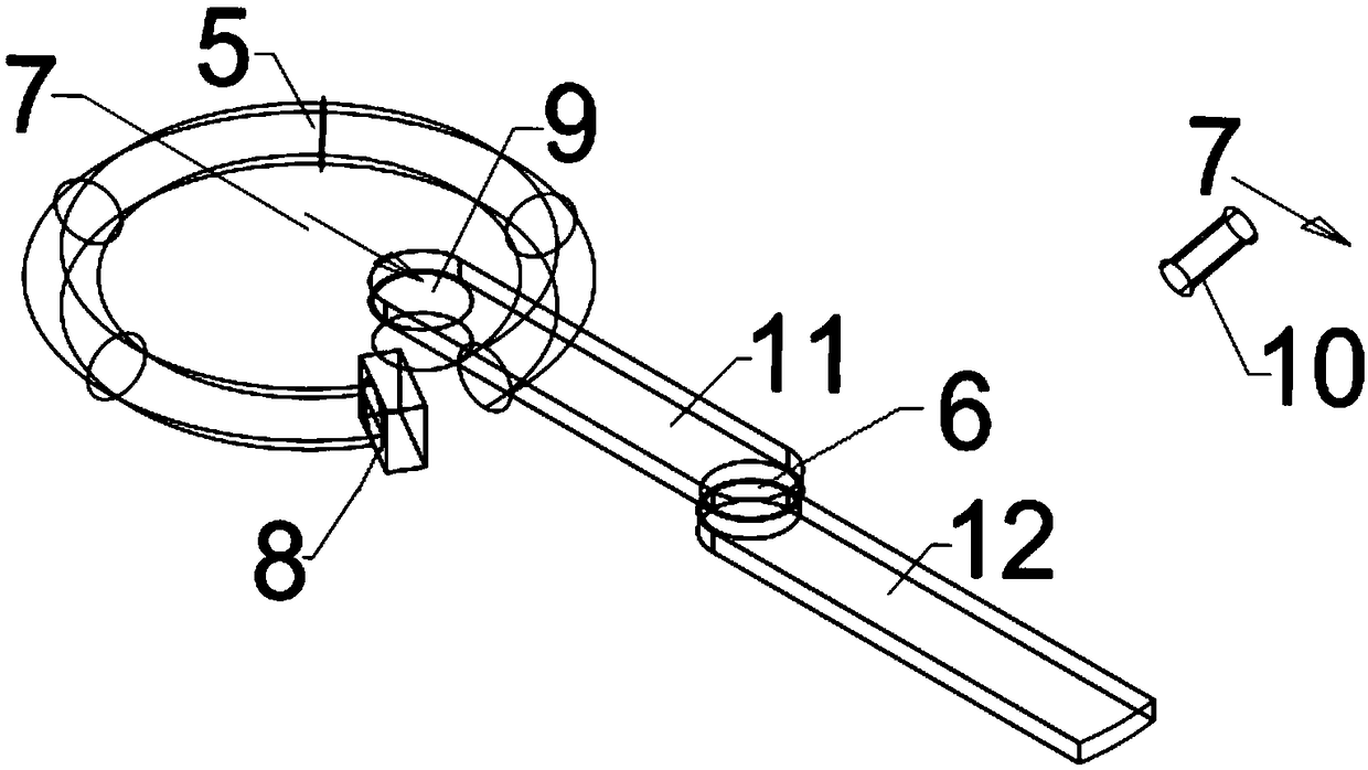
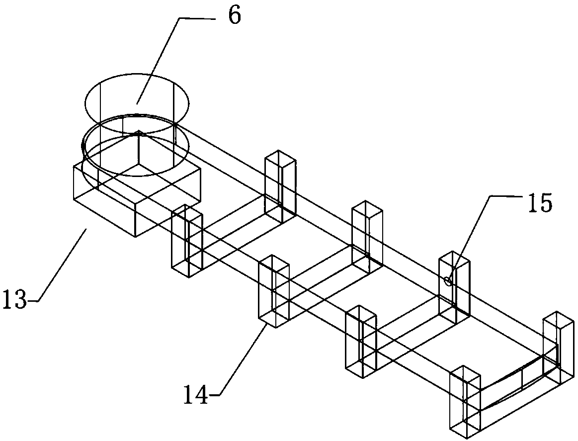
[0020] The present invention is designed as Figure 1-Figure 4 As shown, a concrete hammer device based on a ring spring provided by the patent of the present invention includes a casing 1, a dial 2, a ring spring 5, a double-link device and ancillary components. A casing limit pin hole 4 is arranged on the top of the casing 1, and a reading pointer 7 is arranged on the plane of the ring spring 5 .

[0021] Wherein, in practical application, the ring spring 5 is a circular ring with a notch, and a shock-absorbing elastic washer 8 is provided on the side of the notch.

[0022] Wherein, in practical application, the double linkage device includes a metal linkage 11 , a strike lever 12 and a rotating shaft 9 . One end of the metal connecting rod 11 is hinged on one side of the notch of the annular spring 5 through the first rotating shaft 9 ...


PUM


Abstract

The invention discloses a concrete rebound instrument based on an annular spring. The instrument comprises a fillip bar, a housing, a connecting rod, a pointer and an annular spring with a notch. Oneend of the connecting rod is hinged to the notch side of the annular spring notch, and the other end of the connecting rod is hinged to one end of the fillip bar. The fillip bar is arranged in a normal constraint device. The connecting rod, the pointer and the annular spring with the notch are arranged in the housing. An opening for allowing the fillip bar to move is arranged on the housing. A limiting constraint device which limits the contraction position of the annular spring is arranged on the housing. The pointer points from the center of the annular spring to the hinge portion of the annular spring and the connecting rod. The dial corresponding to the pointer is arranged at a point above a hollow window of the housing. An annular spring is adopted as an energy storage component, curvilinear and linear motions are mutually converted, so that the axial dimension of the instrument can be greatly reduced.

Description

technical field [0001] The patent of the invention relates to the technical field of concrete strength testing instruments, in particular to a novel concrete rebound tester based on an annular spring. technical background [0002] Concrete rebound tester is an instrument used to test the strength of general building components, bridges and various concrete components (slabs, beams, columns, bridges). However, the existing concrete hammer is held by the operator, and the external force is manually applied, and the energy storage of the spring is activated, which has many inconveniences. [0003] Most of the existing patents on concrete rebound hammer are based on the premise of not changing the spring energy storage structure of the rebound hammer, supplemented by external support facilities to improve the accuracy and operability of the measurement, but such measures have not improved Unstable factors during rebound, and the external auxiliary facilities are often too large...

Claims


Application Information

Patent Timeline
Patent Type & Authority Applications(China)
IPC IPC(8): G01N3/52
CPCG01N3/52G01N2203/0035G01N2203/0083
Inventor 何吉曹果叶开
Owner WUHAN UNIV
Learn More