A permanent magnet brushless double-rotor motor
A dual-rotor motor, permanent magnet brushless technology, applied in electrical components, electromechanical devices, synchronous machine parts, etc., can solve the problems of weakened mechanical strength, difficult heat dissipation, commutation loss, etc. , the effect of reducing the amplitude
- Summary
- Abstract
- Description
- Claims
- Application Information
AI Technical Summary
Problems solved by technology
Method used
Image
Examples
Embodiment 1
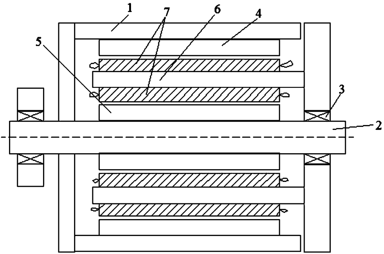
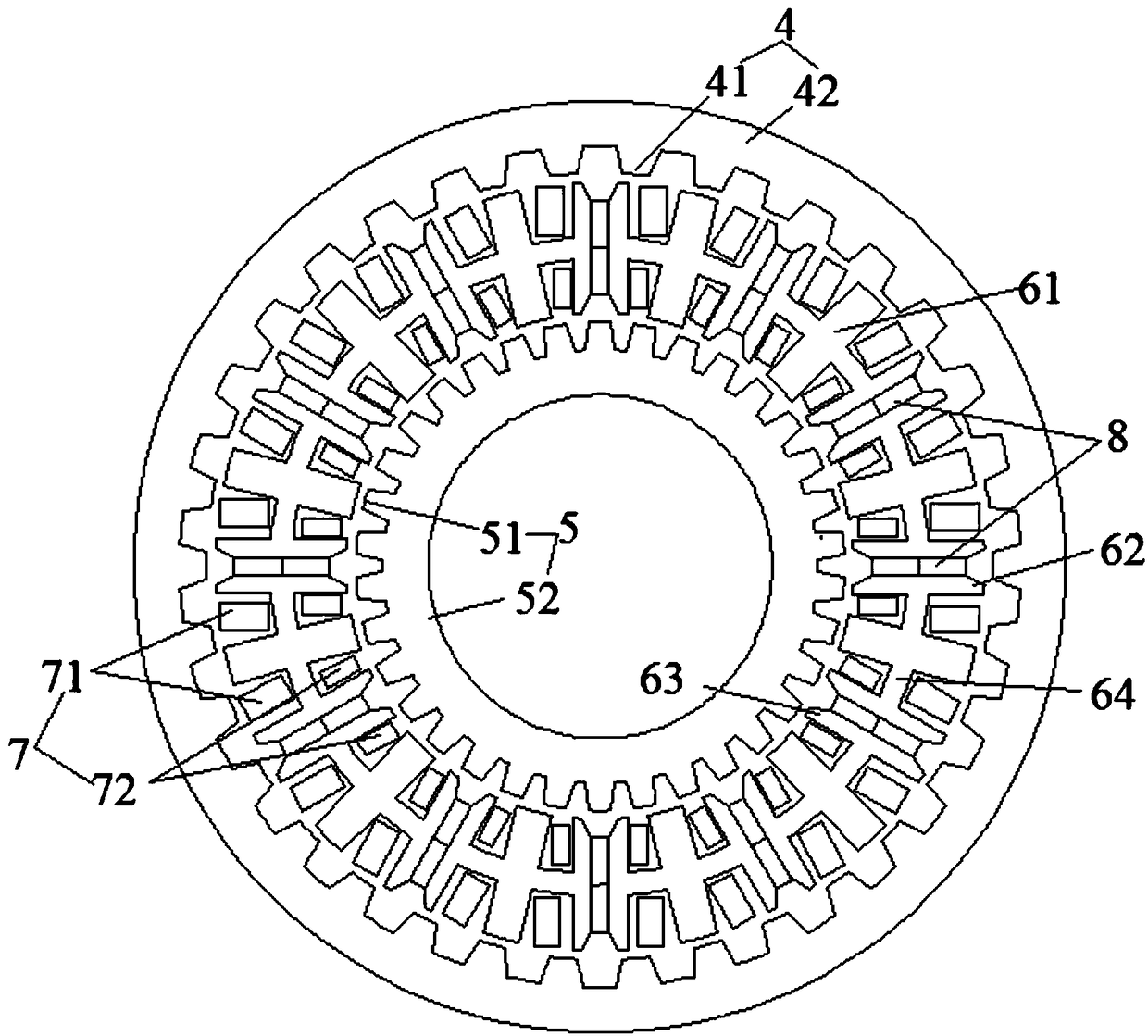
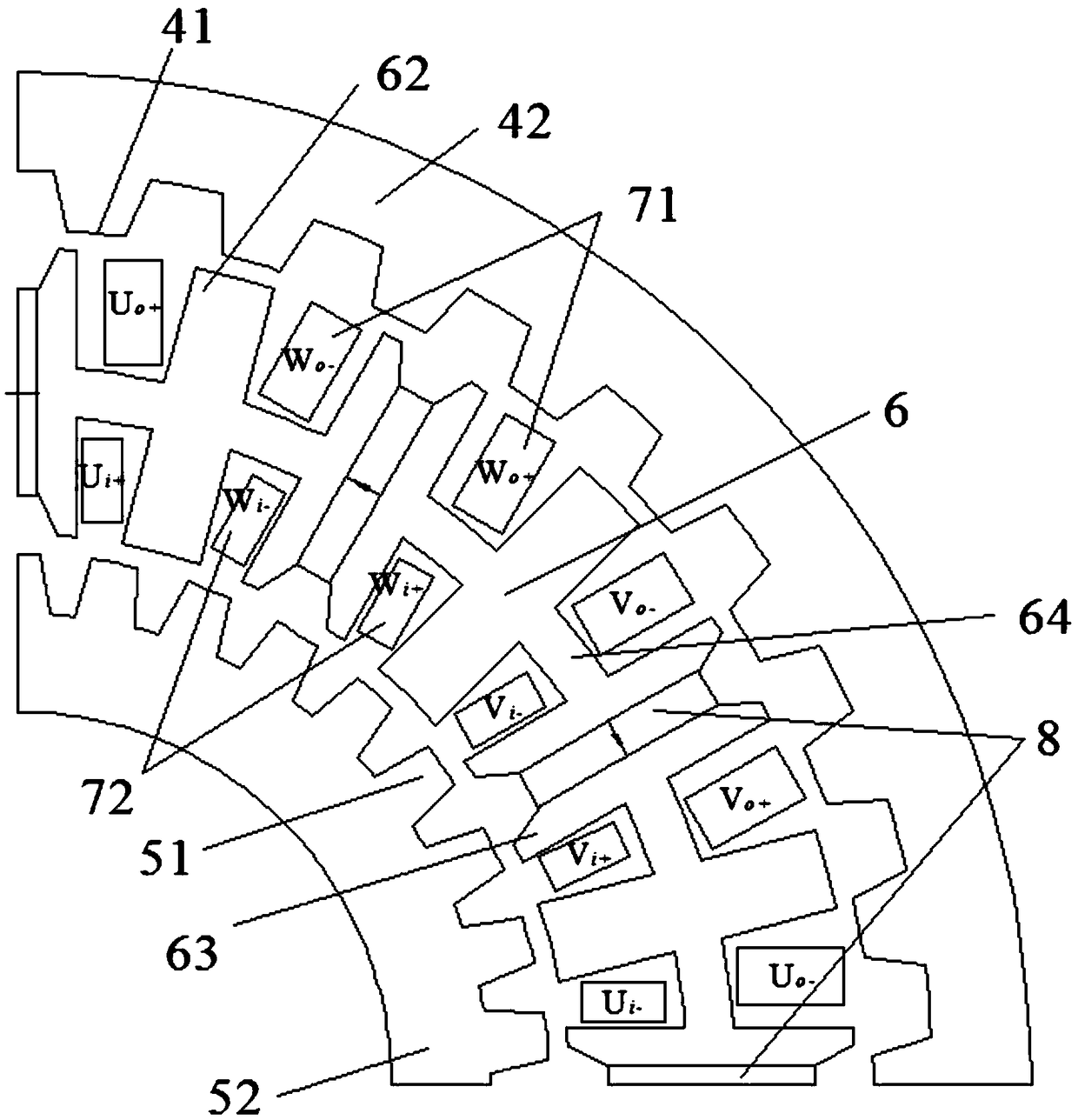
[0031] as attached figure 1 As shown, a permanent magnet brushless dual-rotor motor includes a casing 1, a shaft 2, a bearing 3, an outer salient pole rotor 4, an inner salient pole rotor 5, a stator 6, an armature winding 7 and a permanent magnet 8; The shaft 2 passes through the casing 1; a bearing 3 is arranged between the rear end of the casing 1 and the shaft 2; inside the casing 1, an inner salient pole rotor 5, Stator 6, outer salient pole rotor 4; as attached figure 2 , 3 As shown in and 4, the stator 6 is composed of several double "H"-shaped iron cores 61; permanent magnets 8 are arranged between the adjacent double "H"-shaped iron cores 61; The magnetization direction of the block permanent magnet 8 is opposite. In the figure, the direction of the arrow represents the magnetization direction of the permanent magnet; the stator 6 faces the outer salient pole rotor 4 side is the stator outer tooth 62; the stator 6 faces the inner salient pole On one side of the ro...
Embodiment 2
[0036] The structure of a permanent-magnet brushless double-rotor motor is the same as that in Embodiment 1, except that auxiliary slots 9 are formed on the stator outer teeth 63 and the stator inner teeth 63; Figure 6It is a schematic diagram showing the double "H" type iron core of Example 2. In order to prevent the slotting of the stator outer teeth 62 and the stator inner teeth 63 from introducing new harmonics, the opened auxiliary slots 9 will be strictly symmetrical along the centerline of the stator teeth. In addition, the number of auxiliary slots 9 on each stator tooth is not only one as shown in the figure. After analysis, on the premise of ensuring the performance of the motor, by having auxiliary slots 9 on the stator outer teeth 62 and stator inner teeth 63, the order of the lowest harmonic of the motor cogging torque can be increased, thereby effectively reducing the permanent The cogging torque of the magnetic brushless dual-rotor motor reduces vibration and ...
Embodiment 3
[0038] A permanent magnet brushless double rotor motor, comprising a casing 1, a shaft 2, a bearing 3, an outer salient pole rotor 4, an inner salient pole rotor 5, a stator 6, an armature winding 7 and a permanent magnet 8; the shaft 2 wears through the casing 1; a bearing 3 is arranged between the rear end of the casing 1 and the shaft 2; inside the casing 1, an inner salient pole rotor 5, a stator 6, The outer salient pole rotor 4; the stator 6 consists of several double "H"-shaped iron cores 61; permanent magnets 8 are arranged between the adjacent double "H"-shaped iron cores 61; the and adjacent The magnetization directions of the two permanent magnets 8 are opposite. In the figure, the direction of the arrow represents the magnetization direction of the permanent magnets; the stator 6 faces the outer salient pole rotor 4 side is the stator outer teeth 62; the stator 6 faces the inner convex On one side of the pole rotor 5 are stator inner teeth 63; the connecting portio...
PUM
 Abstract
Description
Claims
Application Information
 - R&D
- Intellectual Property
- Life Sciences
- Materials
- Tech Scout
- Unparalleled Data Quality
- Higher Quality Content
- 60% Fewer Hallucinations
Browse by: Latest US Patents, China's latest patents, Technical Efficacy Thesaurus, Application Domain, Technology Topic, Popular Technical Reports.
© 2025 PatSnap. All rights reserved.Legal|Privacy policy|Modern Slavery Act Transparency Statement|Sitemap|About US| Contact US: help@patsnap.com


