Multifunctional fish feeder

A multi-functional, fish food technology, applied in fish farming, application, climate change adaptation, etc., can solve the problems of inability to store a variety of fish food, difficult to meet the needs of fish at different times, difficult to control the amount of fish food, etc.

Active Publication Date: 2019-01-18
浙江企信检测有限公司
View PDF8 Cites 1 Cited by
  • Summary
  • Abstract
  • Description
  • Claims
  • Application Information

AI Technical Summary

Problems solved by technology

[0004] The above patents cannot store a variety of fish food, and it is difficult to meet the needs of fish at different times; and it is difficult to control the amount of fish food fed

Method used


Image

  • Multifunctional fish feeder
  • Multifunctional fish feeder
  • Multifunctional fish feeder

Examples


Embodiment 1

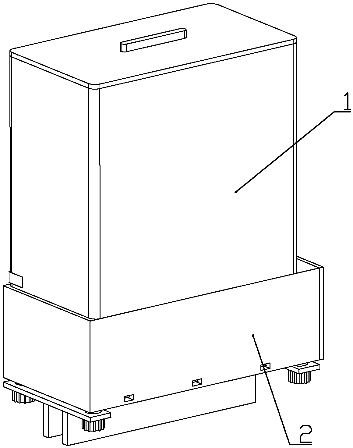
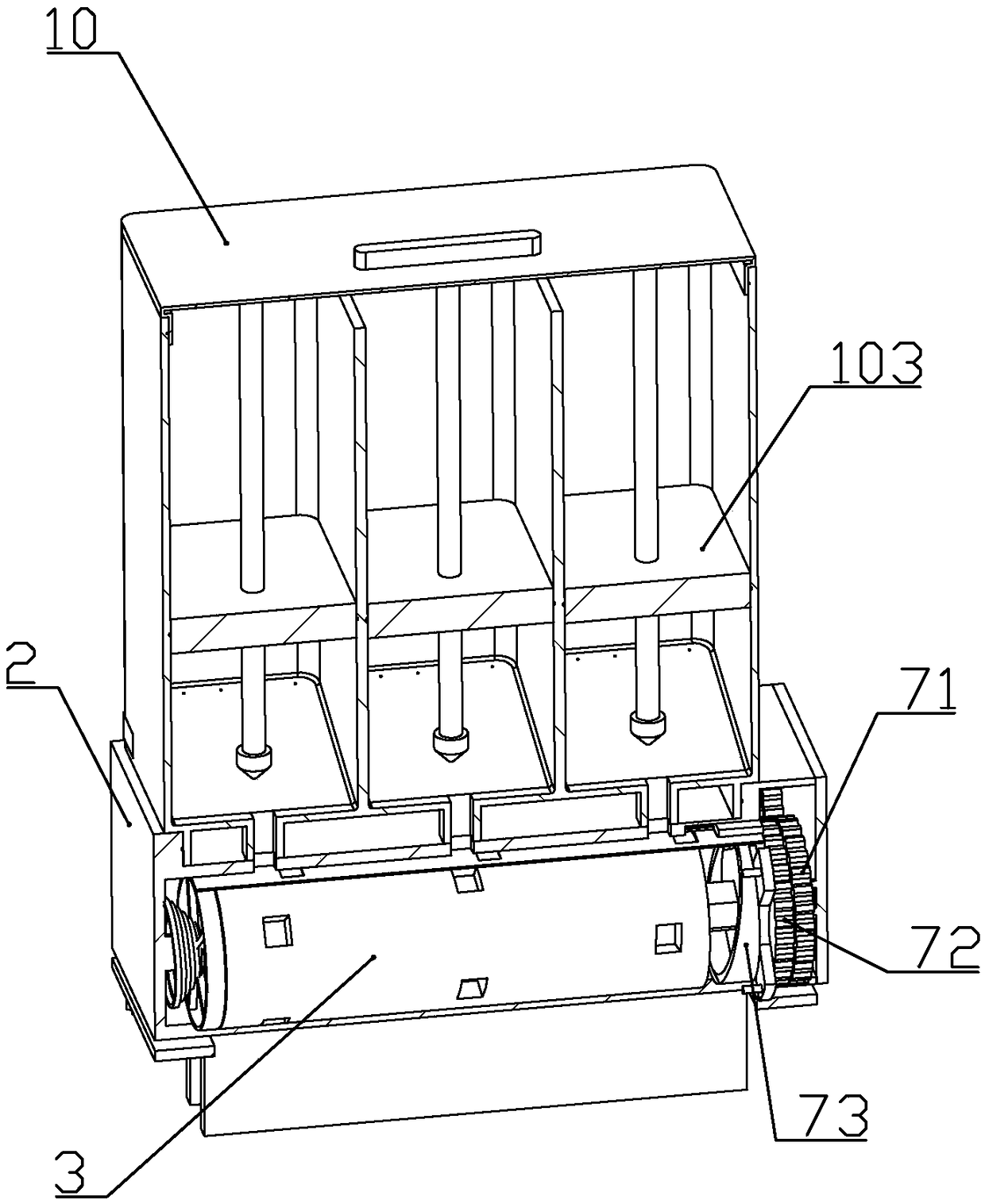
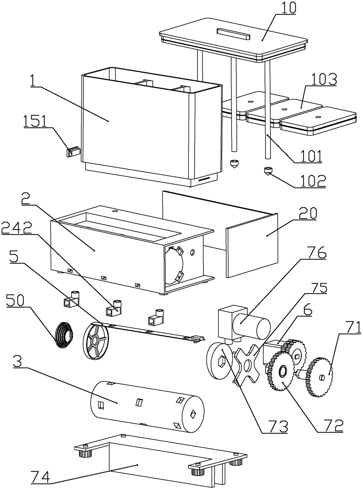
[0055] according to Figure 1 to Figure 17 As shown, a multifunctional fish feeder described in this embodiment includes a base 2, and a material box 1 installed on the upper end of the base, and a material box cover 10 is detachably connected to the material box; A plurality of storage cavities 11 for storing fish food are formed in the box; different types of granular feed can be stored in each storage cavity, so as to provide different types of nutrition for fish.

[0056] The front part of the base is a rotating column installation groove 22 with the axis along the horizontal direction; the side of the rotating column installation groove on the base is a gear installation groove 23, and the rear end of the rotating column installation groove on the base is a motor installation Slot 24.

[0057] The lower end of each storage cavity is formed with a drop tube 13 communicating with the top of the rotating column installation groove.

[0058] The section of the inner bottom ...

Embodiment 2

[0117] according to Figure 17 to Figure 20 As shown, this embodiment makes the following improvements on the basis of Embodiment 1: the lower end of the base is equipped with a foam shell 81 whose lower part extends below the water surface of the fish tank; The foam material tank 813, the foam material connecting plate 811 formed on the upper end of the foam material tank and fixedly connected with the base frame, and the piston sliding groove 812 located on one side of the foam material tank.

[0118] A piston 82 driven by an air pump is connected in sealing and sliding connection in the sliding groove of the piston; a piston spring 83 capable of driving the piston to move upward is installed between the bottom of the sliding groove of the piston and the piston.

[0119] The upper part of the side wall of the sliding groove of the piston is formed with an air outlet 8121 connecting the sliding groove of the piston with the outside world; the diameter of the air outlet is sma...

Embodiment 3

[0133] This embodiment makes the following improvements on the basis of the foregoing embodiments: the upper ends of the valve plates are fixedly connected with sealing gaskets on one side of each material port; The material openings are sealed against each other, so that the material storage chamber is in a closed environment.

[0134] When the controller controls the air pump to pump air in the storage chamber, the storage chamber can be evacuated, so that fish food can be stored better.

[0135] With the operation of the air pump, the air pressure in the material storage chamber decreases, so that the sealing piston moves downward, and always touches the upper end of the fish food. When performing the next air pumping work, it is only necessary to pump out the air below the sealing piston in the material storage chamber. That is, the extraction amount of air is reduced, and the workload of the air pump is reduced.


PUM


Abstract

The invention discloses a multifunctional fish feeder. The feeder comprises a base and a material box, a plurality of storage chambers for storing fish foods are formed in the material box, and a plurality of the fish foods can be stored. Drop tubes are formed in the lower ends of each of the storage chambers. A rotating column is mounted in the base. A plurality of storage tanks with different depths are formed in the outer wall of a rotating column, thereby controlling the fish food consumption for feeding the fishes; a valve piece is axially slidably connected along the rotating column in the base; a material opening is formed in the valve piece. Discharge passages capable of making each of the storage tanks communicated with a fish tank are formed at the lower end of the base. A motorwhich can drive the rotation of the rotating column or the movement of the valve piece is mounted in the base. Each of the storage chambers is in sealing sliding connection with a sealing piston; a gas pump capable of pumping air in the storage chambers is installed in the base; a blowing passage for blowing fish foods from the discharge passages to the front end of the base is formed in the lowerportion of the base; a single stepping motor achieves the control and selection of feeds and the feeding amount. The operation of the gas pump prolongs the storage time of the fish foods and makes the fish foods evenly scattered in the fish tank.

Description

technical field [0001] The invention belongs to the technical field of pet supplies, and in particular relates to a multifunctional fish feeder. Background technique [0002] The Chinese patent document whose document number is CN105746413A discloses a fish feeder, which is characterized in that: the fish feeder includes a storage box, a control device and a timing device, the control device can control the rotation of the storage box, and the timing The device can regularly control the rotation of the storage box through the control device, and the fish feeder can control the rotation of the storage box through the control device, and the food in the storage box will be sprinkled into the fish farming area during the rotation, making the fish feeding operation very easy Convenient and simple, the rotation time of the storage box is set through the timing device, so that the storage box can be rotated at regular intervals, which is convenient for automatic feeding every day,...

Claims


Application Information

Patent Timeline
Patent Type & Authority Applications(China)
IPC IPC(8): A01K61/80
CPCA01K61/80Y02A40/81
Inventor 麻景峰
Owner 浙江企信检测有限公司
Why Eureka
Try Eureka