Efficient wall drilling machine

A punching machine and wall technology, which is applied in the field of decoration and decoration, can solve the problems of low punching positioning accuracy, low work efficiency, and difficult operation, and achieve accurate and effective punching positioning, high punching accuracy and high punching quality , the effect of avoiding pollution

Active Publication Date: 2019-01-18
王勇
View PDF9 Cites 15 Cited by
  • Summary
  • Abstract
  • Description
  • Claims
  • Application Information

AI Technical Summary

Problems solved by technology

[0003] The purpose of the present invention is to provide an efficient wall punching machine for the problems of difficult operation, low work efficiency, and low accuracy of punching positioning when the punching machine punches holes at high places on the wall.

Method used


Image

  • Efficient wall drilling machine
  • Efficient wall drilling machine

Examples


Embodiment 1

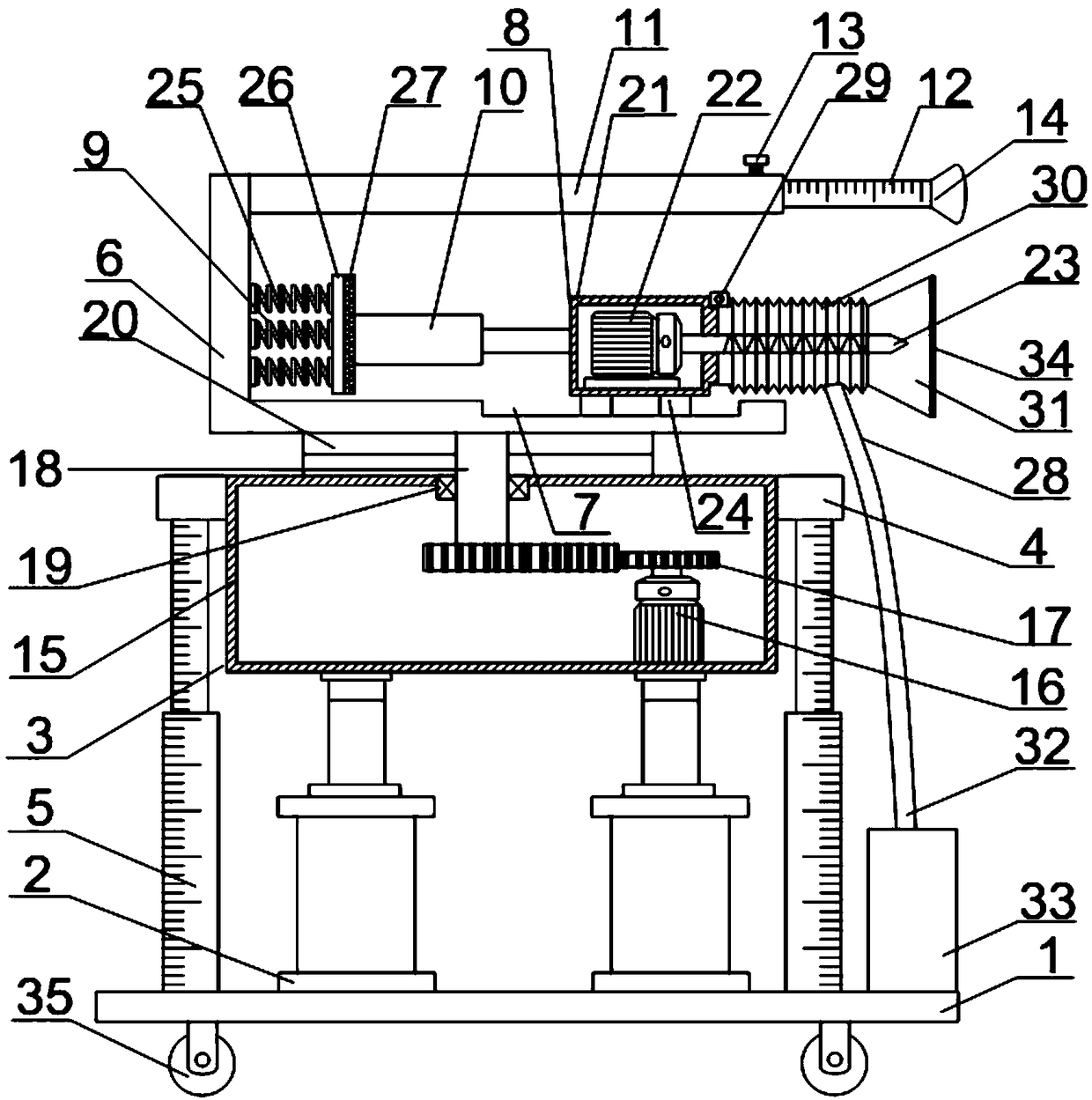
[0025] A high-efficiency wall punching machine includes a base 1, on which a first cylinder 2 is arranged, and the piston rod of the first cylinder 2 is fixedly connected to the lower side of a rotating device 3, and the rotating device 3 Both sides are provided with fixed mounts 4, and the fixed mounts 4 are fixedly connected with telescopic scale rods 5 between the bases 1, and the upper end of the rotating device 3 is connected with a fixed seat 6, and the fixed seat 6 is provided with A chute 7, a punching device 8 is slidably connected in the chute 7, a shock absorber 9 is connected to the fixed base 6 in the vertical direction, the shock absorber 9 is connected to a second cylinder 10, and the first cylinder 10 is connected to the shock absorber 9. The piston rod of the second cylinder 10 is connected to the punching device 8, and the upper end of the fixed seat 6 is fixedly connected with a hollow connecting pipe 11, and the front end of the connecting pipe 11 is inserte...

Embodiment 2

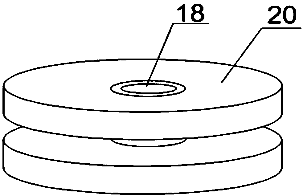
[0028] On the basis of Embodiment 1, the rotating device 3 includes a housing 15, a first motor 16 arranged at the inner bottom of the housing 15, a transmission gear 17 connected to the motor, and a transmission gear 17 connected to the transmission gear 17. The rotating shaft 18 and the rotating disc 20 connected with the rotating shaft 18 through a bearing 19 , the rotating disc 20 is arranged at the outer upper end of the housing 15 .

[0029] In this embodiment, when the direction of punching needs to be changed, the first motor 16 is started, and the transmission gear 17 connected to the first motor 16 drives the rotating shaft 18 to rotate, and the rotating shaft 18 drives the rotating disk 20 connected to it through the bearing 19 to rotate. , so as to drive the fixed seat 6 on the rotating disk 20 and the devices and equipment connected to the fixed seat 6 to rotate, so as to achieve the purpose of changing the punching direction without moving the punching machine, sa...

Embodiment 3

[0031] On the basis of Embodiment 1, the punching device 8 includes a mounting base 21, a second motor 22 fixed in the mounting base 21 and a drill bit 23 fixedly connected to the output end of the second motor 22, the mounting A slider 24 is fixedly connected to the lower end of the seat 21 , and the slider 24 is slidably connected to the chute 7 .

[0032] In this embodiment, when the punching machine is punching, the second motor 22 is started, and the drill bit 23 connected to the output end of the second motor 22 starts to rotate. The slide block 24 at its lower end slides forward in the chute 7, and the second motor 22 fixed in the mounting seat 21 and the drill bit 23 connected to the second motor 22 also carry out punching work forward thereupon, and the punching work does not need manpower. More automation improves the efficiency of drilling work, and the setting of the mounting base 21 can effectively protect the motor and prolong the service life of the motor.


PUM


Abstract

An efficient wall drilling machine comprises a base, a first cylinder is arranged on the base, and a piston rod of the first air cylinder is fixedly connected to the lower side of a rotating device; fixing frames are arranged on the two sides of the rotating device, and a telescopic scale rod is fixedly connected between each fixing frame and the base; the upper end of the rotating device is connected with a fixing base, and a sliding groove is formed in the horizontal direction of the fixing base; a drilling device is slidably connected with the interior of the sliding groove, and a damping device is connected to the vertical direction of the fixing base; the damping device is connected with a second cylinder, and a piston rod of the second cylinder is connected with the drilling device;a hollow connecting pipe is fixedly connected to the upper end of the fixing base, and a scale rod is inserted into the front end of the connecting pipe; the scale rod is fixed into the connecting pipe through a locking bolt, and a vacuum suction cup is arranged at the front end of the scale rod. The drilling machine is reasonable in design, the working efficiency can be effectively improved, thedrilling positioning precision and quality are improved, and the flexibility and the safety are achieved.

Description

technical field [0001] The invention relates to the field of decoration and decoration, in particular to an efficient wall punching machine. Background technique [0002] At present, the interior decoration of many projects requires a punching machine to punch holes on the wall for installation. There are higher requirements for the holes punched in the punching work, and manual hand-held work is performed when punching holes in the high places of the wall. It will be very troublesome. The workers need to build the scaffold first, and then stand on the scaffold with a punching machine to punch holes. It is laborious to build the scaffold, and there is a very big safety hazard for the workers to stand on the scaffold to punch holes, which is harmful to the wall drilling construction. It also caused great inconvenience. And when the punching machine is in use, the rebound force generated by the wall will cause a large vibration. If the manual hand-held punching machine is ope...

Claims


Application Information

Patent Timeline
Patent Type & Authority Applications(China)
IPC IPC(8): B28D1/14B28D7/00B28D7/02B28D7/04
CPCB28D1/14B28D7/00B28D7/005B28D7/02B28D7/046
Inventor 王勇贺刚
Owner 王勇
Why Eureka
Try Eureka