A frame structure with variable facula for sla 3D printer

A printer and variable technology, applied in 3D object support structures, metal processing equipment, manufacturing tools, etc., can solve problems such as poor printing accuracy, changes in light spot positioning, low positioning accuracy and concentricity

Active Publication Date: 2020-08-21
深圳市极光创新科技股份有限公司
View PDF6 Cites 0 Cited by
  • Summary
  • Abstract
  • Description
  • Claims
  • Application Information

AI Technical Summary

Problems solved by technology

[0004] The technical problem to be solved by the present invention is to overcome the defects of low positioning accuracy and concentricity when the variable spot structure is adjusted on the market, and spot positioning changes when the size of the variable spot is switched, leading to poor printing accuracy, and to provide an SLA 3D printer. Variable spot frame structure

Method used


Image

  • A frame structure with variable facula for sla 3D printer
  • A frame structure with variable facula for sla 3D printer
  • A frame structure with variable facula for sla 3D printer

Examples


Embodiment 1

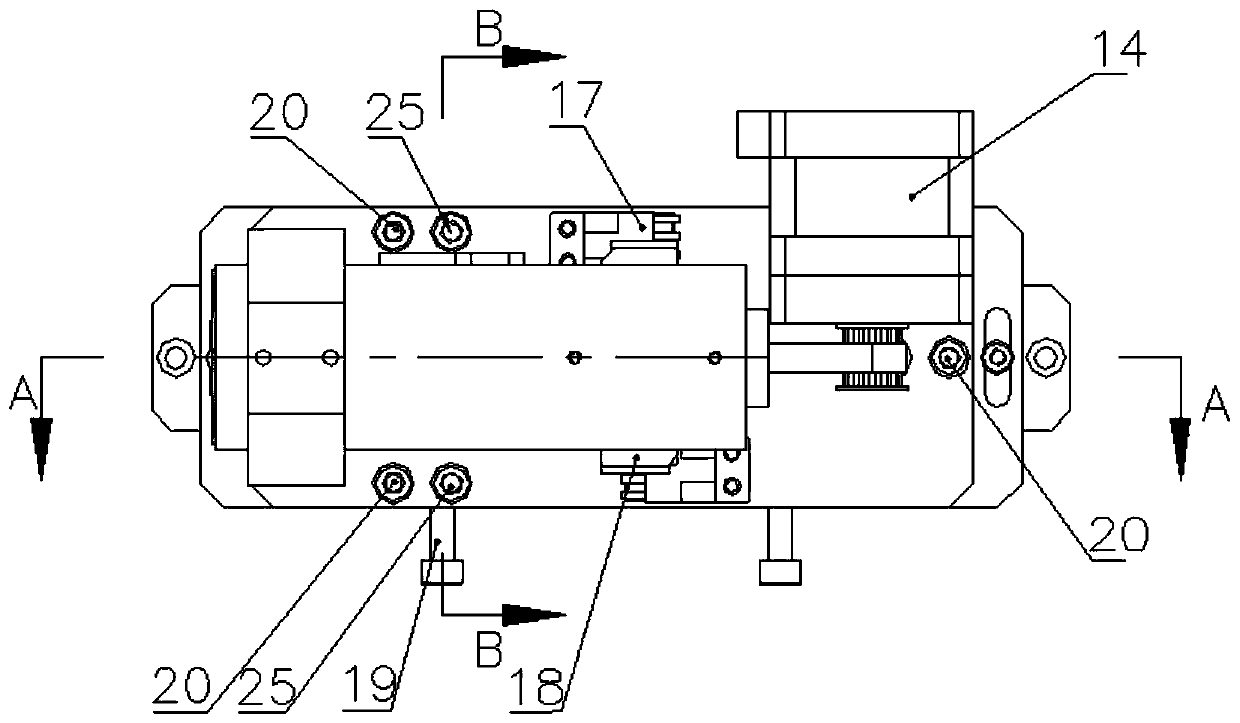
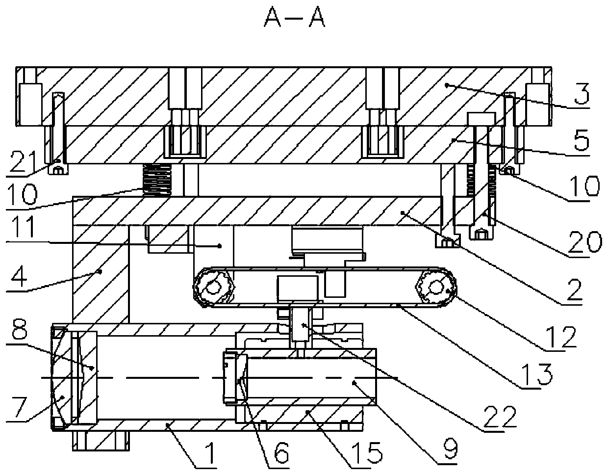
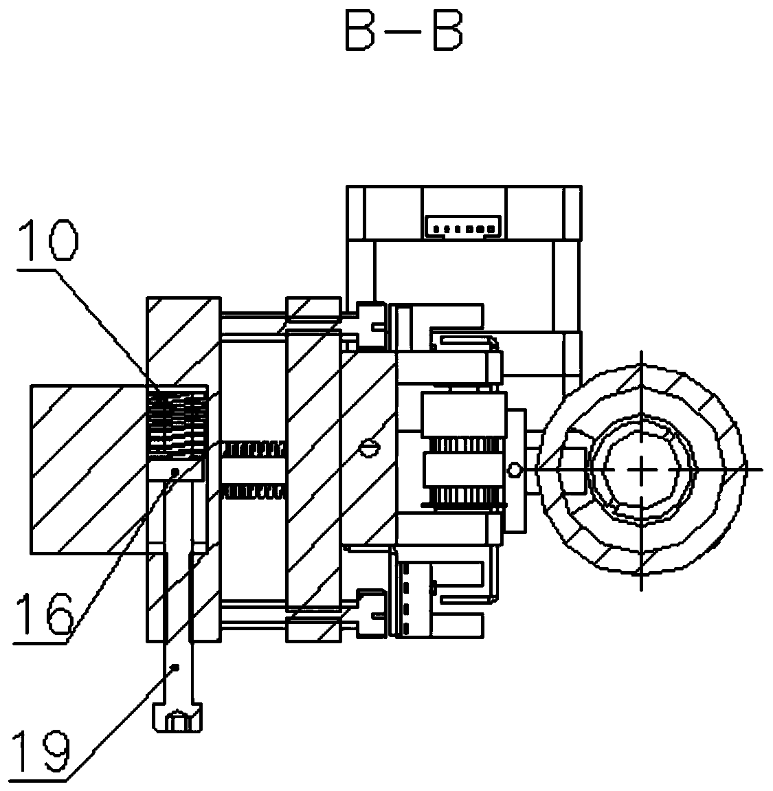
[0019] Such as Figure 1-3 As shown, the present invention provides an SLA 3D printer variable spot frame structure, including a lens barrel 1, a dimming base plate 2, a support 3 and a left and right adjustment plate 5, and the lower end of the support 3 is installed with left and right sides through screws M4X25 21 Adjustment plate 5, and the two ends of left and right adjustment plate 5 are all provided with the elongated screw hole that is used to install screw M4X25 21, and the two ends of left and right adjustment plate 5 sides are all equipped with screw M5X40 19, and screw M5X40 19 and left and right adjustment plate 5 There are springs 10 clamped between them, and the lower end of the left and right adjustment plates 5 is equipped with a dimming bottom plate 2 through screws M5X35 20, and springs 10 are set on the screws M5X35 20, and the springs 10 are clamped on the bottom surface of the left and right adjustment plates 5 and the dimming Between the top surfaces of ...


PUM


Abstract

The invention discloses a variable-spot mirror bracket structure of an SLA 3D printer. The variable-spot mirror bracket structure comprises a supporting base and a left-right regulating plate, whereinthe lower end of the supporting base is provided with the left-right regulating plate through a screw M4X25; the lower end of the left-right regulating plate is provided with a light regulating bottom plate through a screw M5X35; the bottom surface of the light regulating bottom plate is sequentially provided with a lens cone fixing plate, an idle wheel base and a step motor; the lower end of thelens cone fixing plate is fixedly provided with a lens cone; one end inside the lens cone is provided with a convex mirror and a concave mirror; the other end inside the lens cone is provided with amovable mirror sleeve through a linear bearing; one end, located inside the lens cone, on the movable lens sleeve is provided with a movable extending lens; the upper end of a linear bearing is fixedly provided with a movable column; the upper end of the movable column passes through the lens cone and is positioned at the outer side of the top of the lens cone; the step motor and the idle wheel base are in transmission connection with synchronous wheels; a ring-shaped belt is mounted between the two synchronous wheels in a transmitting mode; the lower side surface of the ring-shaped belt is fixedly connected with the top end of the movable column. The concave lens, the convex lens and the extending lens are connected in series to form a combined structure for regulating the sizes of spots,so that the regulating precision is high.

Description

technical field [0001] The present invention relates to a variable light spot frame structure, in particular to a variable light spot frame structure for an SLA 3D printer, which belongs to the technical field of printing equipment. Background technique [0002] The current variable spot structure on the market uses a single lens structure: when the size of the spot changes, use the electric cylinder to drive the expander to stretch and intervene in the optical path. When the spot becomes larger, directly intervene in the expander to make the spot larger. Recovery becomes smaller. When this structure adjusts the light spot, the positioning accuracy and concentricity are low, and the spot positioning will change when the size of the spot is switched, resulting in poor printing accuracy. When switching to a large spot, increasing the transmittance of an expander will lead to loss of power when the size of the spot changes, resulting in poor printing surface quality. [0003]...

Claims


Application Information

Patent Timeline
Patent Type & Authority Patents(China)
IPC IPC(8): B29C64/135B29C64/264B33Y30/00
CPCB29C64/135B29C64/264B33Y30/00
Inventor 林联松
Owner 深圳市极光创新科技股份有限公司
Why Eureka
Try Eureka