A vertical installation and inspection device and installation and inspection method for an optical system

An optical system, vertical technology, applied in the direction of using optical devices, measuring devices, instruments, etc., can solve the problem of uneven shaft hole matching gap, affecting the optical axis consistency and mirror surface shape of the optical system, and imaging defects of optical products. , to achieve the effects of multi-dimensional adjustment, favorable optical axis consistency, simple and feasible device and method

Inactive Publication Date: 2018-07-03
XI'AN INST OF OPTICS & FINE MECHANICS - CHINESE ACAD OF SCI
View PDF6 Cites 0 Cited by
  • Summary
  • Abstract
  • Description
  • Claims
  • Application Information

AI Technical Summary

Problems solved by technology

If the actual use state of the mirror group is not horizontal, or when it is applied in a gravity-free environment, the defects of this installation and inspection method are obvious, that is, due to the gravity of the mirror itself, the shaft-hole fit clearance and stress and deformation are not uniform along the radial direction of the mirror surface. Thus affecting the optical axis consistency and mirror surface shape of the optical system, resulting in imaging defects of optical products, especially for large-aperture optical systems.

Method used


Image

  • A vertical installation and inspection device and installation and inspection method for an optical system
  • A vertical installation and inspection device and installation and inspection method for an optical system
  • A vertical installation and inspection device and installation and inspection method for an optical system

Examples


Embodiment Construction

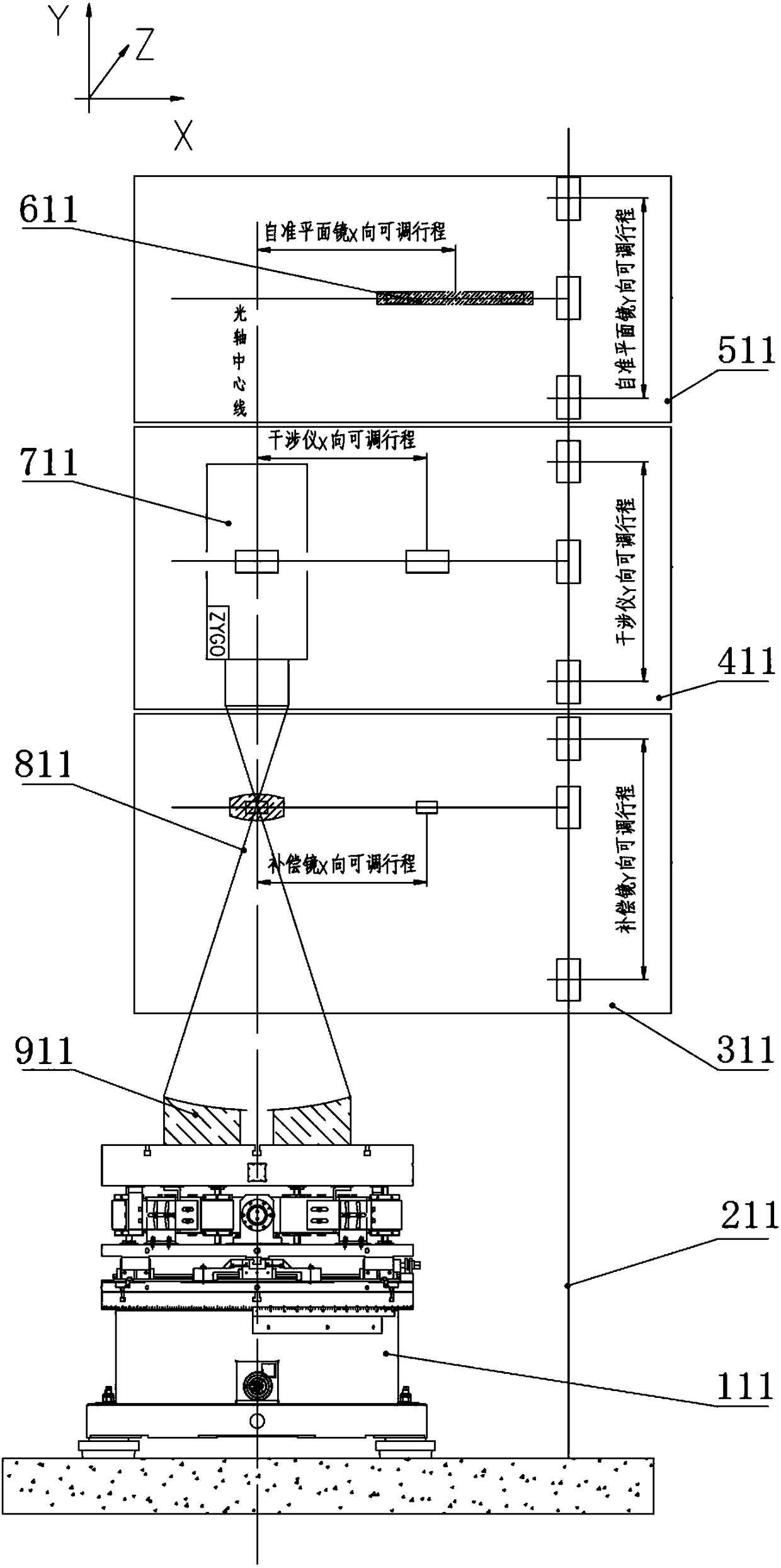
[0047] Such as image 3 As shown, the present invention includes an adjustment turntable 111, the adjustment turntable is used to place the parts to be inspected; three adjustment brackets are sequentially arranged on the adjustment turntable from bottom to top; the three adjustment brackets are installed on a fixed mounting frame 211, respectively It is the compensation mirror adjustment bracket 311, the interferometer adjustment bracket 411 and the self-collimating plane mirror adjustment bracket; the fixed mounting frame is a truss structure with high strength and rigidity welded by section steel;

[0048] The three adjustment brackets all include vertical guide rails and horizontal guide rails. The vertical guide rails are fixedly connected to the fixed mounting frame, and the horizontal guide rails can slide up and down along the vertical guide rails;

[0049] The compensation mirror adjustment bracket also includes a compensation mirror 811; the compensation mirror is ar...


PUM


Abstract

The invention discloses an optical system vertical type installation and detection device, and an optical system vertical type installation and detection method, which belong to the technical field of precision optical application. The optical system vertical type installation and detection device comprises an adjusting turntable and three adjusting brackets arranged on the adjusting turntable from top to bottom in sequence, wherein the adjusting turntable is used for accommodating a part to be installed and detected; the three adjusting brackets are installed on a fixed installation frame, and are respectively a compensating mirror adjusting bracket, an interferometer adjusting bracket and an auto-collimating plane mirror adjusting bracket from bottom to top; and each of three adjusting brackets comprises a vertical guide rail and a transverse guide rail, the vertical guide rail is fixedly connected with the fixed installation frame, and the transverse guide rail can slide up and down along the vertical guide rail. The optical system vertical type installation and detection device and the optical system vertical type installation and detection method can avoid the surface shape problem caused by gravity, can combine and adjust installation and detection optical paths freely, and can satisfy detection requirement of different optical systems.

Description

technical field [0001] The invention belongs to the technical field of precision optics application, and relates to a vertical installation and inspection device and an installation and inspection method of an optical system, which can be applied to the technical field of precision optics application. Background technique [0002] With the development of science and technology in our country, large-aperture optical systems are more and more widely used in the fields of astronomical optics, space remote sensing optics, and space-based target detection and recognition. In the design process of large-aperture optical systems, in order to meet its high rigidity, high strength, and lightweight requirements, special materials and structures are generally used to reduce the stress and deformation of the mirror itself, and reasonable support and matching structures are used to reduce the size of the mirror group. The stress deformation of the system improves the alignment of the opt...

Claims


Application Information

Patent Timeline
Patent Type & Authority Patents(China)
IPC IPC(8): G01B11/24
CPCG01B11/2441
Inventor 康晓鹏付兴李华王鹏刘军鹏
Owner XI'AN INST OF OPTICS & FINE MECHANICS - CHINESE ACAD OF SCI
Why Eureka
Try Eureka