
Novel twistable flapping wing structure and flapping wing twisting method

A wing structure and a new type of technology, applied in the field of bionic aircraft, can solve the problems of increased consumption, increased wing complexity and burden, poor control efficiency, etc., and achieve the effect of simplifying the structure

Pending Publication Date: 2019-01-18
SHANGHAI MARITIME UNIVERSITY
View PDF0 Cites 1 Cited by
  • Summary
  • Abstract
  • Description
  • Claims
  • Application Information

AI Technical Summary

Problems solved by technology

[0003] In the prior art, an active twisting mechanism is used for twisting flapping wings. This method requires an additional twisting mechanism and energy input, which increases the complexity and burden of the wing; the twisting mechanism is controlled from the base of the wing. For wings with chord ratio, the control efficiency of the distal end of the wing is weak, and the control efficiency is poor; in addition, for independent flat flapping and twisting, it is necessary to control their frequency input separately, which increases consumption

Method used


Image

  • Novel twistable flapping wing structure and flapping wing twisting method
  • Novel twistable flapping wing structure and flapping wing twisting method
  • Novel twistable flapping wing structure and flapping wing twisting method

Examples


Embodiment 1

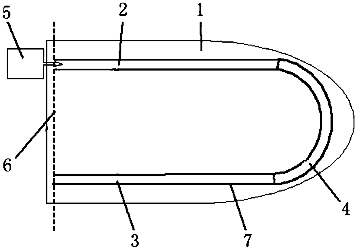
[0075] A new type of twistable flapping wing structure, including wings, pipes, and pumps. The root of the wing is a flapping shaft, and the wings perform flapping vibration around the flapping shaft. The pipeline is located inside the wing, and the pipe Including an inflow section, a connection section and an outflow section, the pump communicates with the pipeline, and the pump circulates the fluid in the pipeline.

[0076] The ducts are arranged spanwise inside the wing.

[0077] The inflow section is located at the leading edge of the wing.

[0078] The outflow section is located at the trailing edge of the wing.

Embodiment 2

[0080] A flapping wing twisting method adopts a twistable flapping wing structure, the twistable flapping wing structure includes wings, pipes, and pumps, the root of the wing is a flapping wing shaft, and the wings perform flapping vibration around the flapping wing shaft , the pipeline is located inside the wing, the pipeline includes an inflow section, a connection section and an outflow section, the pump communicates with the pipeline, and the pump circulates the fluid in the pipeline.

[0081] The ducts are arranged spanwise inside the wing.

[0082] The inflow section is located at the leading edge of the wing.

[0083] The outflow section is located at the trailing edge of the wing. The torsion frequency is automatically matched with the flapping frequency.

[0084] Turn on the pump to circulate the fluid in the pipeline, so that the twist can be generated during the flapping process.

[0085] Evaluation Test One

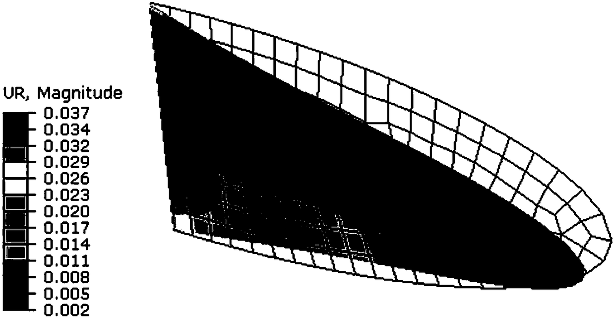
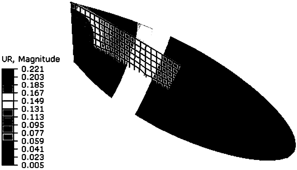
[0086] The finite element software Abaqus is used t...


PUM

PropertyMeasurementUnit
Densityaaaaaaaaaa
Elastic modulusaaaaaaaaaa

Abstract

A novel twistable flapping wing structure comprises at least a wing, a pipe and a pump, wherein the root of the wing is a flapping wing shaft, the wing vibrates around the flapping wing shaft, the pipe is located inside the wing, the pipe comprises an inflow section, a connecting section and an outflow section, the pump is in communication with the pipe, and the pump circulates fluid in the pipe.The novel twistable flapping wing structure provided by the invention has the advantages of simple and efficient control, automatic frequency matching, and remarkable effect on the wing with high aspect ratio.

Description

technical field [0001] The invention relates to the field of bionic aircraft, in particular to a twistable flapping wing structure and a flapping wing twisting method. Background technique [0002] The insect flapping-wing aircraft belongs to the bionic aircraft. Insects fly by flapping their wings, which simultaneously generate lift and thrust. The flapping wing is similar to the motion of a propeller, and the wings undergo periodic flat flapping motions and spanwise twists. By twisting, it is ensured that each section maintains approximately the same angle of attack with the incoming flow, thereby improving aerodynamic performance. [0003] In the prior art, an active twisting mechanism is used for twisting flapping wings. This method requires an additional twisting mechanism and energy input, which increases the complexity and burden of the wing; the twisting mechanism is controlled from the base of the wing. For wings with a chord ratio, the control efficiency of the ...

Claims


Application Information

Patent Timeline
IPC IPC(8): B64C33/02
CPCB64C33/02
Inventor 侯丹肖烜仲政殷雅俊
Owner SHANGHAI MARITIME UNIVERSITY
Learn More