Eureka AIR delivers breakthrough ideas for toughest innovation challenges, trusted by R&D personnel around the world.

Non-initiating unlocking device and locking and unlocking method thereof

An unlocking device and non-pyrotechnic technology, which is applied in the docking device of aerospace vehicles, transportation and packaging, space navigation equipment, etc., can solve the problem of hot knife assembly volume and weight, the rope is easy to form carbon fragments, and the hot knife assembly is reliable. Low reliability and other problems, to achieve the effect of strong connection reliability, light weight and simple structure

Active Publication Date: 2019-01-18
BEIJING RES INST OF SPATIAL MECHANICAL & ELECTRICAL TECH
View PDF6 Cites 9 Cited by
  • Summary
  • Abstract
  • Description
  • Claims
  • Application Information

AI Technical Summary

Problems solved by technology

[0004] In the existing release and separation device based on hot knife cutting, the hot knife needs to rely on the push part to move along the knife groove, resulting in a large volume and weight of the hot knife assembly, which is not suitable for the aerospace field that has strict requirements for light weight; in addition, the current After the rope is carbonized by the hot knife assembly, during the cutting process, the sheet-shaped hot knife exerts a radial thrust on the rope, causing the carbonized part of the rope to easily form carbon fragments and pollute the space environment; in addition, the pushing part of the existing hot knife assembly Spring preload is often used to push the hot knife to move along the knife groove. In a long-term space environment, the spring is prone to aging and plastic deformation under stress, resulting in performance degradation and low reliability of the hot knife assembly.

Method used


Image

  • Non-initiating unlocking device and locking and unlocking method thereof
  • Non-initiating unlocking device and locking and unlocking method thereof
  • Non-initiating unlocking device and locking and unlocking method thereof

Examples


Embodiment Construction

[0068] The specific implementation manners of the present invention will be further described in detail below in conjunction with the drawings and specific embodiments.

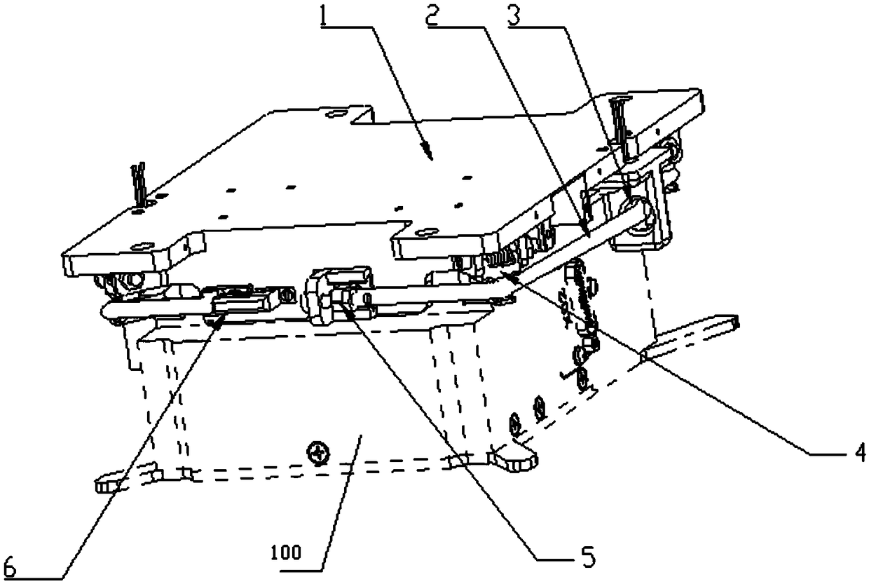
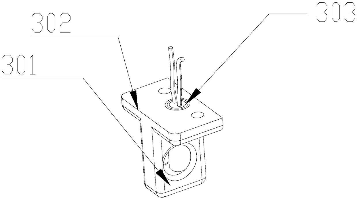
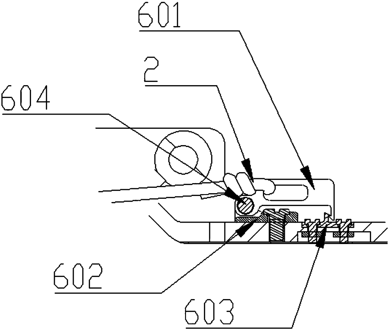
[0069] see figure 1 , the embodiment of the present invention provides a non-firework unlocking device for locking or unlocking the first part (not shown in the figure) and the second part 100, including a fastening rope 2, a hot knife assembly 3 and at least Two lock release parts 4, the lock release parts 4 are used to be fixed on the first part, the fastening rope 2 surrounds the second part 100, and provides tightening force to the lock release part 4 Make the lock release part 4 in the first state to lock the second part 100, the hot knife assembly 3 includes a hot knife 303 and a hot knife installation part 301, the hot knife installation part 301 is made of heat insulating material, The hot knife 303 is arranged in the hot knife installation part 301, the fastening rope 2 passes through the hot knife ...


PUM


Abstract

The invention provides a non-initiating unlocking device and a locking and unlocking method thereof, which belongs to the field of unlocking devices. The device comprising a fastening cord, A hot knife assembly and at least two locking release members, the lock release member is used for fixing on the first member and the lock release member is used for fixing on the first member, the fastening cord is for providing a tightening force to the lock release member such that the lock release member locks the second member in a first state, the hot knife assembly comprises a hot knife and a hot knife mounting part, The hot knife mounting part is made of heat insulating material, the hot knife is arranged in the hot knife mounting part, the fastening rope is in close contact with the hot knife,and the hot knife is an electric heating element for generating heat to fuse the fastening rope, so that the locking releasing part returns to the second state and releases the second part. The invention avoids the carbonaceous fragments caused by the radial thrust, and the hot knife and the hot knife mounting part are structured under the space environment, and the performance is stable and the reliability is high.

Description

technical field [0001] The invention relates to a non-pyrotechnic unlocking device and a locking and unlocking method, belonging to the field of unlocking devices. Background technique [0002] Locking and unlocking are the key technologies for spacecraft in-orbit flight, and are used to realize key actions such as solar wing deployment, antenna deployment, and payload release. Existing starships and weapon models mostly use pyrotechnic devices for connection and release actions. The main advantages of traditional pyrotechnic unlocking devices are: high reliability, large energy storage, fast action speed, simple and compact structure, quality and volume Small size and low cost, but because the pyrotechnic device relies on the explosion or combustion of gunpowder to drive the functional mechanism to complete the task, the pyrotechnic device has a working process that cannot be overcome by itself. Disadvantages such as gas, debris, etc. polluting the space environment and di...

Claims


Application Information

Patent Timeline
Patent Type & Authority Applications(China)
IPC IPC(8): B64G1/64B64G1/44
CPCB64G1/443B64G1/645B64G1/64F42B15/36
Inventor 贾子年张文峰麻翠杨立欣方渊刘世毅任法璞张威
Owner BEIJING RES INST OF SPATIAL MECHANICAL & ELECTRICAL TECH
Why Eureka
Eureka Blog
Learn More