Supercharge Your Innovation With Domain-Expert AI Agents!

Insulation material processing equipment

A technology for processing equipment and thermal insulation materials, which is applied in the field of thermal insulation material processing, can solve the problems of increasing the production cost of thermal insulation materials, increasing the labor intensity of operators, and waste of raw materials and product quality, so as to reduce labor intensity, optimize performance, and improve connection. intensity effect

Pending Publication Date: 2019-01-18
德清县世纪龙保温材料厂
View PDF15 Cites 0 Cited by
  • Summary
  • Abstract
  • Description
  • Claims
  • Application Information

AI Technical Summary

Problems solved by technology

[0003] In the prior art, when producing thermal insulation materials, materials are loaded by manual feeding. On the one hand, this feeding method increases the labor intensity of the operators; Waste of raw materials or unqualified product quality increases the production cost of insulation materials

Method used


Image

  • Insulation material processing equipment
  • Insulation material processing equipment

Examples


Embodiment 1

[0028] Thermal insulation material processing equipment is used to produce thermal insulation materials.

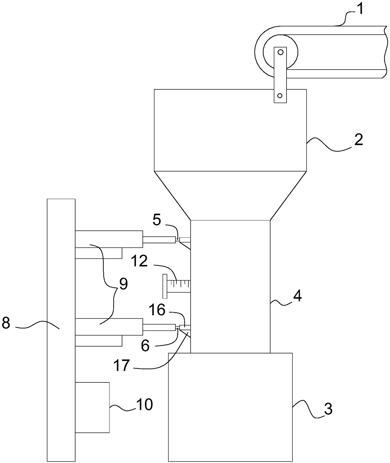
[0029] Such as figure 1 , the thermal insulation material processing equipment includes a conveyor belt 1, a silo 2 and a production box 3, and the conveyor belt 1, the silo 2 and the production box 3 are all conventional structures in the prior art, and will not be described here, and those skilled in the art can easily obtained through purchase.

[0030] The conveyor belt 1 transmits the raw materials to the silo 2 , and a discharge pipe 4 for discharging the raw materials in the silo 2 into the production box 3 is arranged between the silo 2 and the production box 3 .

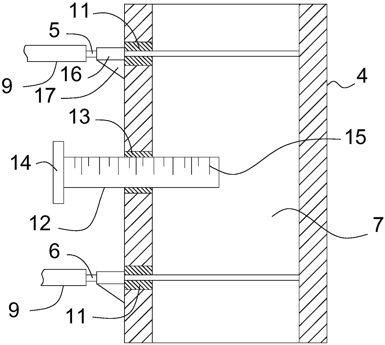
[0031] Such as figure 1 , figure 2 , the cross-sectional shape of the discharge pipe 4 is rectangular, and a quantitative mechanism for controlling the discharge amount of the discharge pipe 4 is arranged in the discharge pipe 4, and the quantitative mechanism includes blocking the discharge pipe T...

Embodiment 2

[0038] This embodiment is an optimization scheme for embodiment 1 in combination with embodiment 1.

[0039] Such as figure 1 , figure 2 , the discharge pipe 4 is also provided with an adjustment column 12 for adjusting the volume of the quantitative space 7, the cross-sectional shape of the adjustment column 12 is circular, and the adjustment column 12 is inserted into the discharge pipe 4, the discharge pipe 4 is provided with a hole that cooperates with the adjustment column 12, the side wall of the hole is bonded with an elastic ring 13, and the adjustment column 12 is provided with a handle 14 , the handle 14 is located outside the quantitative space 7 , and a scale line 15 is provided on the adjustment column 12 . This scale line 15 indicates the volume of the regulating cylinder 12 which is located in the dosing space 7 .

[0040] The handle 14 is covered with a rubber sleeve, and a pattern is arranged on the rubber sleeve, and the scale line 15 is recessed into the...

Embodiment 3

[0043] This embodiment introduces the installation method of the upper sealing plate 5 and the lower sealing plate 6 in combination with the embodiment 1 or the embodiment 2.

[0044] Such as figure 1 , figure 2, on the discharge pipe 4 are respectively provided with guide rods 16 guiding the upper sealing plate 5 and the lower sealing plate 6, there are two pairs of guide rods 16, and the guide rods 16 can be welded on the discharge pipe 4 , the guide rods 16 are respectively provided with guide grooves that cooperate with the upper sealing plate 5 and the lower sealing plate 6, the guide rods 16 are located outside the quantitative space 7, and, in the discharge pipe 4 and the guide rod 16 are provided with support ribs 17 . The supporting rib 17 is welded between the guide rod 16 and the discharge pipe 4 .

[0045] Two cylinders 9 are fixed on the frame 8 by bolts. Two cylinders 9 also can be fixed on the frame 8 by other means.


PUM


Abstract

The invention discloses insulation material processing equipment to solve the technical problem, so that the insulation material can be supplied conveniently and the quantity of the material can be controlled conveniently. According to the insulation material processing equipment, an upper sealing plate and a lower sealing plate are arranged in a discharge tube. A quantitative space is formed by the upper sealing plate, the lower sealing plate and a part of the inner cavity of the discharge tube. When raw materials are measured, the upper sealing plate is pulled out to make the raw materials enter the quantitative space. Then the upper sealing plate is reset to block the discharge tube; when the materials are discharged, the lower sealing plate is pulled out, and the material located in the quantitative space can be discharged. The upper sealing plate blocks the discharge tube, so the quantity of the raw materials discharged from the discharge tube is the quantity of the quantitative space. According to the scheme, the discharge quantity of the discharge tube can be controlled conveniently, and the performance of the insulation material production equipment is optimized. The insulation material production equipment can be automatically loaded with the installation of a conveyor belt and a bin, thereby reducing the labor intensity of operators.

Description

technical field [0001] The invention relates to processing equipment, in particular to thermal insulation material processing equipment, and belongs to the field of thermal insulation material processing. Background technique [0002] The thermal insulation material is a material with thermal insulation capability, which is widely used in the prior art. Insulation materials need to be produced in production boxes during the production process, that is, raw materials need to be added to the production box for production. [0003] In the prior art, when producing thermal insulation materials, materials are loaded by manual feeding. On the one hand, this feeding method increases the labor intensity of the operators; Waste of raw materials or unqualified product quality increases the production cost of insulation materials. Contents of the invention [0004] The technical problem to be solved by the present invention is to provide thermal insulation material processing equip...

Claims


Application Information

Patent Timeline
Patent Type & Authority Applications(China)
IPC IPC(8): B65D90/64
CPCB65D90/64
Inventor 姚志强
Owner 德清县世纪龙保温材料厂
Features
  • R&D
  • Intellectual Property
  • Life Sciences
  • Materials
  • Tech Scout
  • Unparalleled Data Quality
  • Higher Quality Content
  • 60% Fewer Hallucinations
Learn More