
High-speed gluey splicing device for banding materials

A technology of splicing device and splicing device, which is applied in the direction of winding strips, thin material handling, transportation and packaging, etc., can solve the problem of incompetence of lap splicing device, etc., so as to reduce downtime and cycle, reduce production cost, guarantee The effect of production efficiency

Pending Publication Date: 2019-01-18
HENAN XINZHILIN ELECTROMECHANICAL DEVICE CO LTD
View PDF0 Cites 0 Cited by
  • Summary
  • Abstract
  • Description
  • Claims
  • Application Information

AI Technical Summary

Problems solved by technology

Faced with such a wide raw material, the lapping device on the KDF2 filter rod forming machine is obviously not competent

Method used


Image

  • High-speed gluey splicing device for banding materials
  • High-speed gluey splicing device for banding materials
  • High-speed gluey splicing device for banding materials

Examples


Embodiment 1

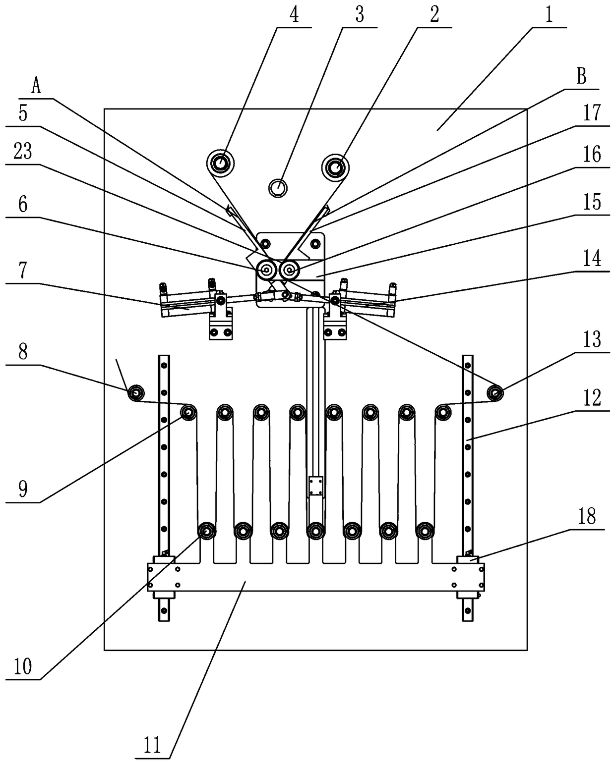
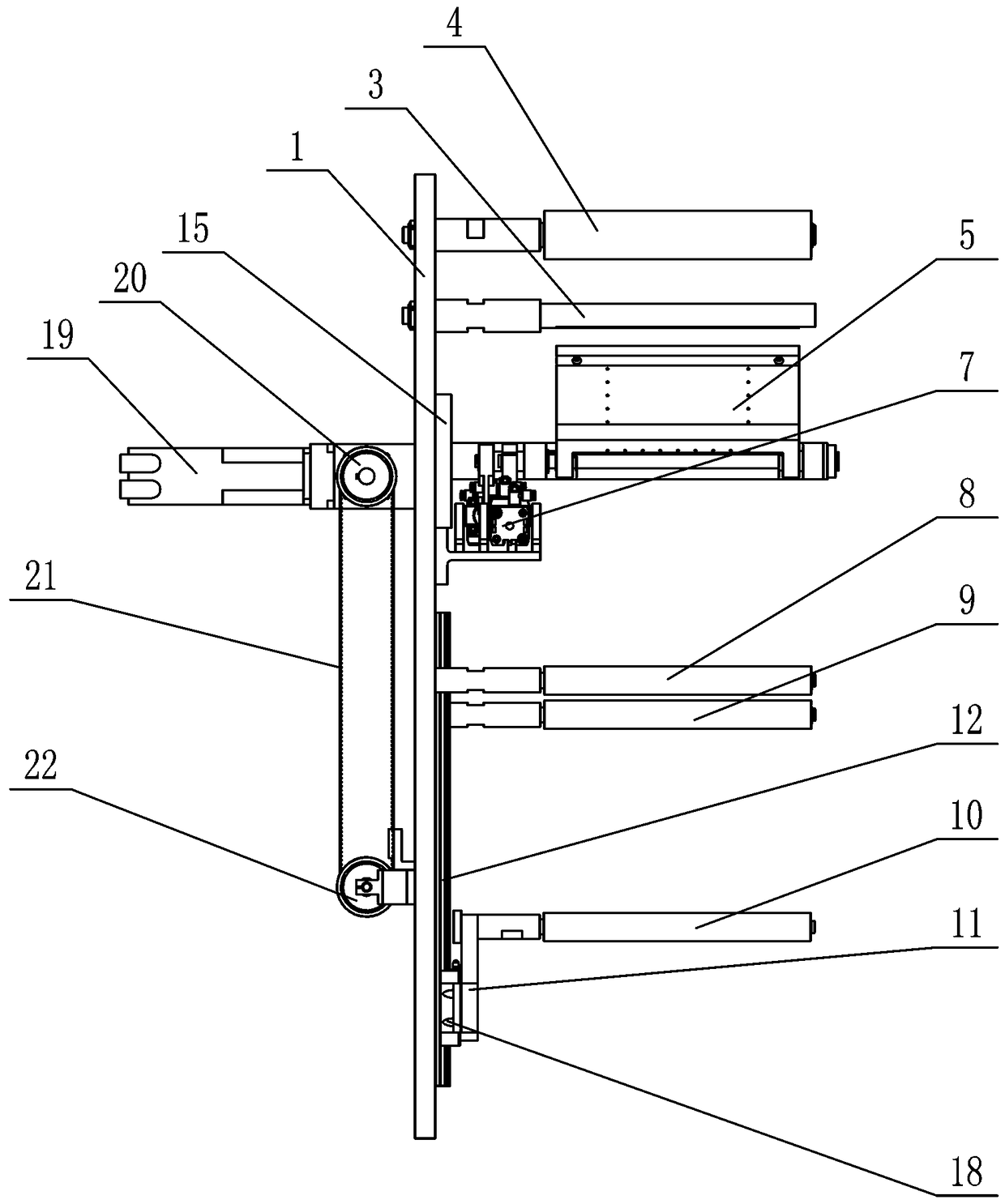
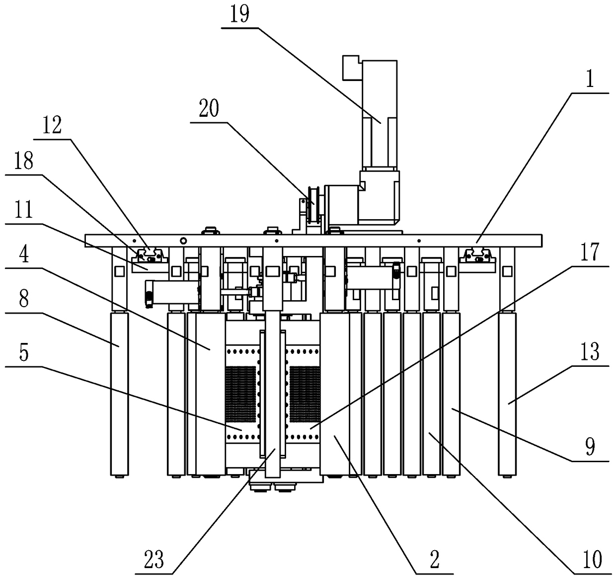
[0033] Such as Figure 1~6As shown, a high-speed adhesive splicing device for strip-shaped materials includes a base plate 1, a left guide roller 4, a right guide roller 2, a cutting roller 3, an overlapping device, a buffer device, a buffer feed roller 13 and a buffer discharge roller 8 , the left guide roller 4 and the right guide roller 2 are all arranged on the bottom plate 1, and rotate relative to the base plate 1, the left guide roller 4 is connected with the raw material roll of the old strip material through the strip material, and the right guide roller 2 passes through The new strip-shaped material is connected with the raw material roll of the new strip-shaped material, and the cutting roller 3 is arranged on the base plate 1 between the left guide roll 4 and the right guide roll 2, and the base plate 1 is provided with an overlapping device, so Described overlapping device comprises overlapping frame 15, joint guide roller 23, left crimping plate 5, right crimping...

Embodiment 2

[0042] Such as Figure 7 Shown, repeat embodiment one, have the following difference, when normal production, the first section of new strip-shaped material is pulled out under the action of negative pressure and sticks on the right crimping plate 17, and the single-sided glue Half is bonded with the head end of the new strip material, the other half of the single-sided adhesive is exposed, and the side of the single-sided adhesive without glue and the new strip material are attached to the right crimping plate 17 under negative pressure, When the strip material needs to be spliced, the left cylinder 7 moves to drive the old strip material to the right crimping plate 17. The knife 55 cooperates with the cutting roller 3 to cut off the old material, the left crimping plate 5 and the right crimping plate 17 are closely attached under the action of the left cylinder 7, and the old strip material is bonded to the exposed single-sided adhesive, thereby realizing Butt joint of new ...


PUM


Abstract

The invention provides a high-speed gluey splicing device for banding materials. The device comprises a left pressing joint plate and a right pressing joint plate which are overlapped, the left pressing joint plate and the right pressing joint plate suck the tail sections of the old banding materials and the head sections of the new banding materials through negative pressure respectively, and aredriven by air cylinders to conduct inward patting separately, the tail sections and the head sections, smeared with bonding glue, of the old banding materials and the new banding materials are pattedto be spliced together, and the new and old banding materials are spliced; meanwhile, a buffering device is arranged and stores the banding materials with certain lengths, when the banding materialsare spliced, the banding materials stored by the buffering device are released and put into production, thus the normal production speed is not influenced, the banding materials are spliced without halting or speed reduction, thus the production efficiency is guaranteed, and the production cost is lowered.

Description

Technical field: [0001] The invention belongs to the technical field of strip sheet material processing and forming equipment, and in particular relates to a high-speed glued splicing device for strip material. Background technique: [0002] In the production process of the tobacco production industry, there are a large number of raw materials in the shape of strip coil paper; such as cigarette paper in traditional tobacco, cigarette box lining paper; segment of PLA material. One of the problems that must be faced with tape coil materials is that after the materials are consumed, the old tape coil materials need to be removed and new tape coil materials installed. At present, in the process of changing the strip paper material, the equipment must be shut down, which will inevitably affect the production efficiency. Due to the limitations of machines and manpower, it is impossible to make the raw material paper coils particularly large, coupled with the step-by-step increas...

Claims


Application Information

Patent Timeline
Patent Type & Authority Applications(China)
IPC IPC(8): B65H19/18B65H19/14B65H19/20
CPCB65H19/14B65H19/1821B65H19/20B65H2701/1944B65H2701/1133
Inventor 屈步峰吕新磊时书凯海运峰李雷
Owner HENAN XINZHILIN ELECTROMECHANICAL DEVICE CO LTD
Learn More