Automatic tape attaching device

A gluing device and automatic technology, applied in the directions of transportation and packaging, sending objects, thin material processing, etc., can solve the problems of easy wrinkling of manual gluing and hard breaking of manual cutting, so as to avoid wrinkling defects and easy cutting , the effect of smooth cut

Pending Publication Date: 2019-01-18
THERMAL GROUP TECH HUIZHOU
View PDF0 Cites 2 Cited by
  • Summary
  • Abstract
  • Description
  • Claims
  • Application Information

AI Technical Summary

Problems solved by technology

[0003] Aiming at the shortcomings of the prior art that manual glue is easy to wrinkle and manual cutting glue is not easy to break, this application discloses an automatic glue sticking device

Method used


Image

  • Automatic tape attaching device
  • Automatic tape attaching device
  • Automatic tape attaching device

Examples


Embodiment 1

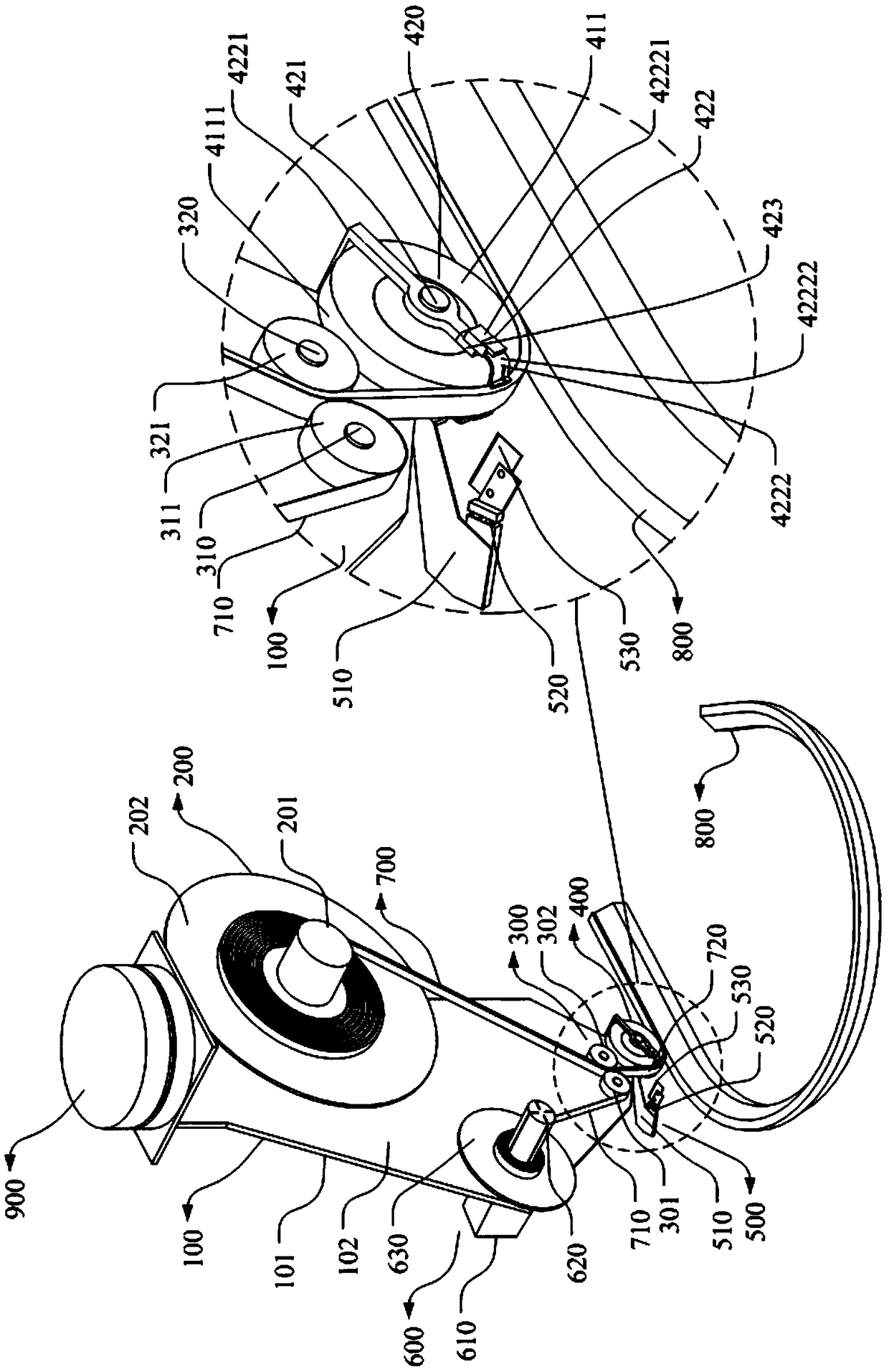
[0053] The present application provides an automatic gluing device for pasting foam glue on a plane of a product to be glued, wherein the foam glue has a release paper and foam adhered to the release paper through an adhesive film. Such as Figure 1-4 As shown, they are three-dimensional structural schematic diagrams of the automatic gluing device in this embodiment when preparing for gluing, during gluing, cutting and finishing gluing. The automatic gluing device of the present application includes a fixed bracket 100 , a feeding mechanism 200 , a separation mechanism 300 , a gluing mechanism 400 , a gluing cutting mechanism 500 and a release paper recycling mechanism 600 . Among them, the fixed bracket 100 is used to support the discharging mechanism 200, the separation mechanism 300, the glue application mechanism 400, the glue cutting mechanism 500 and the release paper recovery mechanism 600, the discharging mechanism 200 is located above the fixed bracket 100, and the se...

Embodiment 2

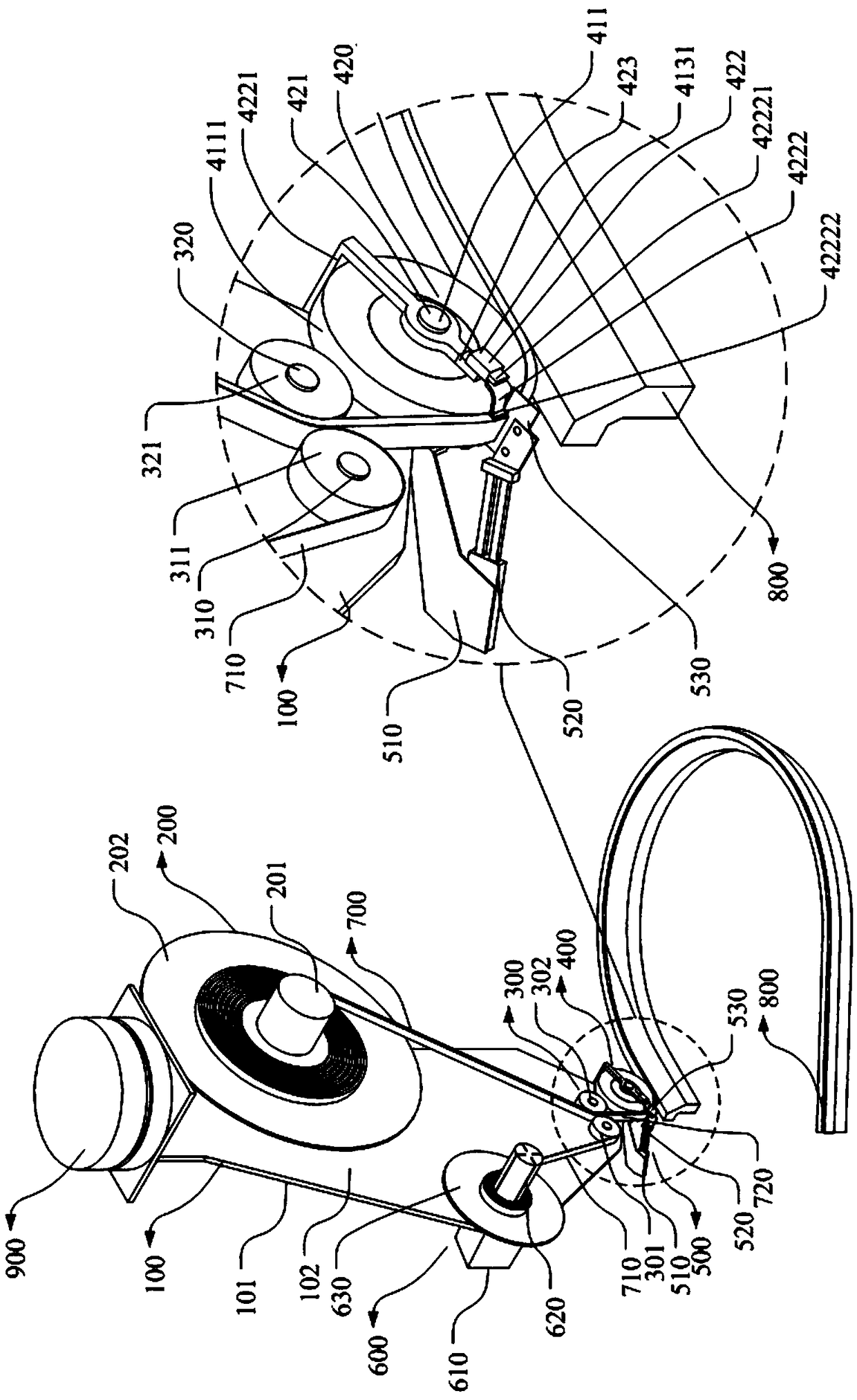
[0064] The difference between this embodiment and the first embodiment lies in that the structure of the gluing mechanism is different, and the structure of the gluing mechanism in this example is simpler than that of the gluing mechanism in the first embodiment. Such as Figure 9-14 As shown, the three-dimensional structure schematic diagram of the automatic gluing device is ready for gluing, gluing process, glue cutting and gluing is completed, and the side view of the gluing mechanism and the gluing cutting mechanism, and the gluing cutting mechanism is fixed on the foam after cutting the foam Schematic diagram of the length of the foam on the wheel surface of the third driving wheel. The gluing mechanism 400 includes a third rotating driving part 410 and a third driving wheel 411; the third rotating driving part 410 is arranged on the second surface 102 of the fixed bracket 100, and the third driving wheel 411 is fixedly sleeved on the third rotating driving part 410 of t...


PUM


Abstract

The invention discloses an automatic tape attaching device. The device comprises a fixing bracket, a pay-off mechanism, a separating mechanism, a tape attaching mechanism, a tape cutting mechanism anda release paper recycling mechanism, and the pay-off mechanism, the separating mechanism, the tape attaching mechanism, the tape cutting mechanism and the release paper recycling mechanism are arranged on the fixing bracket. Foam tape is designed into a coil to wind a pay-off reel, in the tape attaching process, the rotation power output of a first rotation driving part, a second rotation drivingpart and a third rotation driving part is respectively controlled, and a first driving wheel, a second driving wheel and a third driving wheel are controlled to be simultaneously started and stoppedaccordingly; as long as it is ensured that the linear speeds of the first rotation driving part, the second rotation driving part and the third rotation driving part are the same and equal to the linear speed required for tape attaching, the rotation linear speeds of the first driving wheel, the second driving wheel and the third driving wheel can be synchronous with the linear speed required fortape attaching, and the defects are overcome that the foam tape has certain elasticity and is easily elongated in the attaching process, and wrinkles are caused by elongation after the foam tape is attached.

Description

technical field [0001] The present application relates to the technical field of gluing machines, in particular to an automatic gluing device. Background technique [0002] Foam glue is slender, soft and elastic, and consists of release paper and foam glued through the film. In order to facilitate manual gluing, the foam glue is usually designed as a long strip, and the length and width correspond to the length and width of the product to be glued respectively. When gluing by hand, the production speed is 50 pieces / hour / person. Due to the elasticity of the foam glue, the strength cannot be controlled during the manual glue application process. The foam glue will be stretched to different degrees before it is attached to the product to be glued. The elongated foam glue produces a lot of wrinkling. And, because the foam glue is relatively soft, when cutting glue manually, it is difficult to control the cutting direction of the reciprocating blade for cutting, and the foam gl...

Claims


Application Information

Patent Timeline
Patent Type & Authority Applications(China)
IPC IPC(8): B65H35/07
CPCB65H35/06
Inventor 姜文新邓中应谭弘平
Owner THERMAL GROUP TECH HUIZHOU
Why Eureka
Try Eureka