The Design Method of Orbiter Wheel Path Based on Wrinkle Defect Consideration

A design method and wrinkle wheel technology, applied in metal processing equipment, geometric CAD, metal processing, etc., to avoid wrinkling defects and improve forming quality

Active Publication Date: 2021-09-24
NORTHWESTERN POLYTECHNICAL UNIV
View PDF0 Cites 0 Cited by
  • Summary
  • Abstract
  • Description
  • Claims
  • Application Information

AI Technical Summary

Problems solved by technology

However, most of the existing research results are qualitatively analyzing the rationality of various types of rotary wheel paths from the perspective of improving forming accuracy and minimizing stress-strain and wall thickness reduction rate, which are only effective for specific working conditions
There is still a lack of standards to design a wheel path that avoids flange wrinkling

Method used


Image

  • The Design Method of Orbiter Wheel Path Based on Wrinkle Defect Consideration
  • The Design Method of Orbiter Wheel Path Based on Wrinkle Defect Consideration
  • The Design Method of Orbiter Wheel Path Based on Wrinkle Defect Consideration

Examples


Embodiment 1

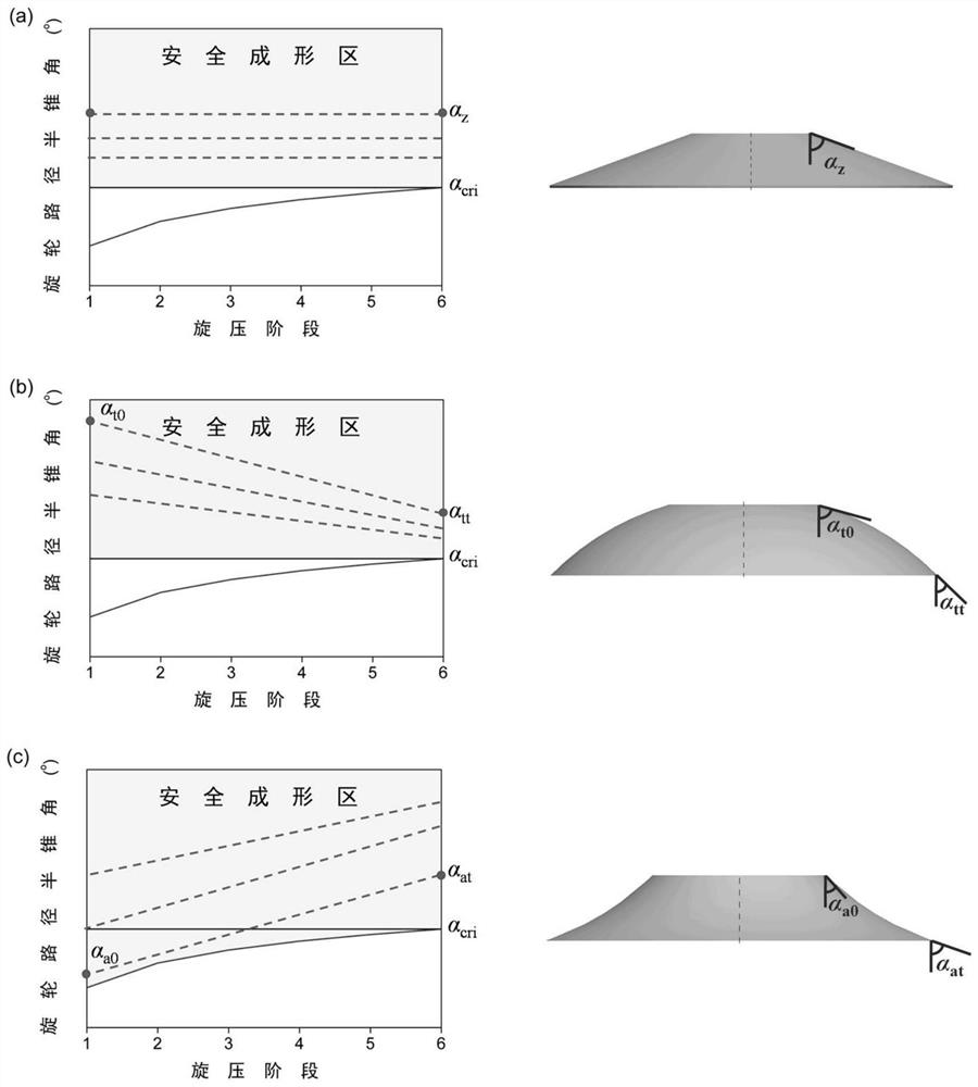
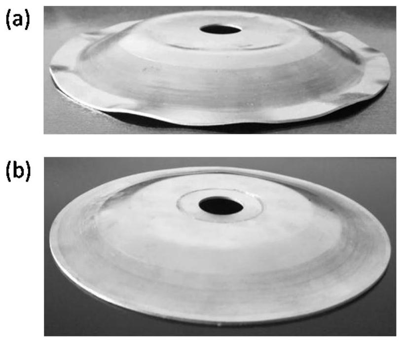
[0030] Embodiment one: for the aluminum alloy conical curved surface target member of 60 ° semi-cone angle, according to figure 2 It can be seen from (a) that the component cannot be formed by single-pass general spinning under the existing forming conditions, and its flange will have serious wrinkling defects during the single-pass general spinning process ( image 3 (a)), so the multi-pass general rotation wheel path design is carried out on this component. Based on the method proposed by the present invention, the slab is loaded along the rotary wheel path that is 2° higher than the half-cone angle of the multi-pass critical wrinkling rotary wheel path, and the formed aluminum alloy conical curved surface member is as follows image 3 As shown in (b), the flange does not have wrinkle defects during the general spinning process.

Embodiment 2

[0031] Embodiment 2: For the aluminum alloy convex surface target member (α t0 = 80°, α tt =70°), using the method proposed by the present invention, it can be calculated and obtained under the existing forming conditions in a single pass general rotation α cri =62.5°, according to figure 2 (b) It is considered that the convex curved surface member can be universally formed by a single pass. The formed aluminum alloy convex surface experimental components such as Figure 4 As shown, the flange did not produce wrinkle defects during the single-pass spinning process.

[0032] The key technology of the present invention is to propose a method for designing the path of the swirling wheel based on the consideration of wrinkling defects. This method can successfully avoid the wrinkling defects of the slab during the swirling process and effectively improve its forming quality. This method is suitable for single-pass and multi-pass general rotation forming technology of curved s...


PUM


Abstract

The invention discloses a design method of a spiral wheel path based on wrinkling defect considerations. The design method includes the following steps of establishing a critical semi-cone angle model of a linear spiral wheel path considering the wrinkle defect in combination with the characteristics of general mechanics. The initial width of the flange is divided into i sections, so that the flange is in the critical wrinkling state at the end of each section of the path, and the half-cone angle curve of the critical wrinkling wheel path of the first pass can be obtained. The half-cone curve for a given surface member generatrix is ​​compared to the half-cone curve for the first-pass critical corrugating wheel path. Segmentation is repeated until the generatrix half-cone angle of a given curved surface member is within the safe forming area above the half-cone angle curve of the final pass critical corrugating roller path. The semi-cone angle of the spinner path in each spinning pass is larger than the half-cone angle of the critical wrinkling spinner path to avoid flange wrinkling defects. The invention can quickly and effectively design the rotary wheel path, successfully avoids the wrinkling defect of the slab during the general spinning process, and effectively improves the forming quality.

Description

technical field [0001] The invention relates to the field of sheet material forming and processing, and relates to a design method of a critical wheel path considering wrinkling defects, which is mainly used in the design of the wheel path to avoid wrinkling defects during the general rotation process of a slab. Background technique [0002] Metal sheet spinning is a local plastic deformation process. The slab clamped by the tail crown and the mandrel produces local plastic deformation due to the force of the wheel. With the high-speed rotation of the mandrel and the feed movement of the wheel, the local plastic deformation The deformation gradually extends to the entire slab. Due to the unique advantages of small forming force and high forming performance, metal sheet spinning process plays an important role in the manufacture of aviation, aerospace and civil products. According to the change of plate thickness, metal sheet spinning can be divided into two categories: gene...

Claims


Application Information

Patent Timeline
Patent Type & Authority Patents(China)
IPC IPC(8): B21D22/14B21C51/00G06F30/17
CPCB21C51/00B21D22/14
Inventor 詹梅高鹏飞陈淑婉马飞张洪瑞
Owner NORTHWESTERN POLYTECHNICAL UNIV
Why Eureka
Try Eureka