Centrifugal pump low in failure rate

A centrifugal pump, failure rate technology, applied to pumps, parts of pumping devices for elastic fluids, pump components, etc., can solve the problems of parts being easily damaged by corrosion, unstable performance, and high operating noise, etc., to achieve The effect of prolonging service life, reducing failure rate and reducing noise

Active Publication Date: 2019-01-18
ANHUI WOLONG PUMP & VALVE CO LTD
View PDF7 Cites 0 Cited by
  • Summary
  • Abstract
  • Description
  • Claims
  • Application Information

AI Technical Summary

Problems solved by technology

Existing centrifugal pumps have problems such as high operating noise, parts that are easily damaged by corrosion, unstable performance, high failure rate in operation, and short service life, etc., and further improvement is urgently needed

Method used


Image

  • Centrifugal pump low in failure rate
  • Centrifugal pump low in failure rate
  • Centrifugal pump low in failure rate

Examples


Embodiment 1

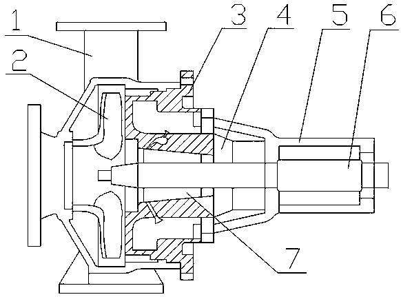
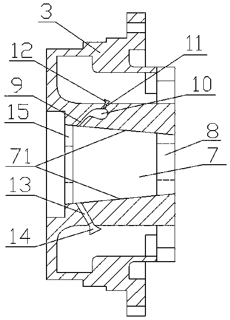
[0026] A centrifugal pump with stable use and long service life, including a pump body 1, an impeller 2, a pump cover 3, a mechanical seal gland 4, a suspension 5 and a rotating shaft 6, the pump cover 3 is fixed on one side of the pump body 1, The pump chamber for installing the impeller 2 is formed between the pump cover 3 and the pump body 1, the suspension 5 is fixed on one side of the pump cover 3, the rotating shaft 6 is supported in the suspension 5 through a bearing, and one end of the rotating shaft 6 extends into the pump chamber , the impeller 2 is placed in the pump cavity of the pump body 1 and fixed on the end of the shaft 6, a mechanical seal cavity 7 for installing a mechanical seal is provided between the pump cover 3 and the shaft 6, and a positioning mechanical seal is installed on the outside of the pump cover 3 The mechanical seal gland 4, the pump cover 3 is provided with a central through hole 8, the mechanical seal chamber 7 is located on the side of the...

Embodiment 2

[0040] A centrifugal pump with a low failure rate, including a pump body, an impeller, a pump cover, a mechanical seal gland, a suspension and a rotating shaft, the pump cover is fixed on one side of the pump body, and an impeller is formed between the pump cover and the pump body The pump chamber, the suspension is fixed on one side of the pump cover, the rotating shaft is supported in the suspension by the bearing, and one end of the rotating shaft extends into the pump chamber, the impeller is placed in the pump chamber of the pump body and fixed on the end of the rotating shaft, A mechanical seal chamber for installing a mechanical seal is provided between the pump cover and the rotating shaft, and a mechanical seal gland for positioning the mechanical seal is installed on the outside of the pump cover. The through hole faces one side of the pump body of the centrifugal pump and is connected with the central through hole. The mechanical seal chamber is in the shape of a tru...

Embodiment 3

[0054] A centrifugal pump with a low failure rate, including a pump body, an impeller, a pump cover, a mechanical seal gland, a suspension and a rotating shaft, the pump cover is fixed on one side of the pump body, and an impeller is formed between the pump cover and the pump body The pump chamber, the suspension is fixed on one side of the pump cover, the rotating shaft is supported in the suspension by the bearing, and one end of the rotating shaft extends into the pump chamber, the impeller is placed in the pump chamber of the pump body and fixed on the end of the rotating shaft, A mechanical seal chamber for installing a mechanical seal is provided between the pump cover and the rotating shaft, and a mechanical seal gland for positioning the mechanical seal is installed on the outside of the pump cover. The through hole faces one side of the pump body of the centrifugal pump and is connected with the central through hole. The mechanical seal chamber is in the shape of a tru...


PUM


Abstract

The invention discloses a centrifugal pump low in failure rate. The centrifugal pump comprises a pump body, an impeller, a pump cover, a machine seal gland, a suspension frame and a rotating shaft, wherein the pump cover is fixed to one side of the pump body, a pump cavity for installing the impeller is formed between the pump cover and the pump body, the suspension frame is fixed to one side of the pump cover, and the rotating shaft is supported in the suspension frame through a bearing; one end of the rotating shaft extends into the pump cavity, the impeller is arranged in the pump cavity ofthe pump body and is fixed at the end of the rotating shaft, and a machine sealing cavity is in a circular truncated cone shape; the cross section of the machine sealing cavity is in a trapezoid shape, and an air guiding channel is formed in the inner wall of the machine sealing cavity; the air guiding channel is connected with an air storage cavity in the pump cover, the upper portion of the airstorage cavity is connected with an exhaust channel, and a drainage channel is further formed in the inner wall of the machine sealing cavity; a cooling plate is further arranged in the machine sealing cavity, and the inner wall of the machine sealing cavity is subjected to surface enhanced modification. The centrifugal pump is low in fault rate, and has high market competitiveness and application and popularization value.

Description

technical field [0001] The invention relates to a centrifugal pump, in particular to a centrifugal pump with low failure rate. Background technique [0002] Centrifugal pump refers to the pump that transports liquid by the centrifugal force generated when the impeller rotates. It can transport more media. It is a common power machine in modern people's daily life and industrial production. The existing centrifugal pumps have problems such as high noise in operation, easy corrosion and damage of parts, unstable performance, high failure rate in operation, and short service life. Further improvement is urgently needed. Contents of the invention [0003] The object of the present invention is to provide a centrifugal pump with low failure rate aiming at the existing problems. [0004] The present invention is achieved through the following technical solutions: [0005] A centrifugal pump with a low failure rate, including a pump body, an impeller, a pump cover, a mechanical...

Claims


Application Information

Patent Timeline
Patent Type & Authority Applications(China)
IPC IPC(8): F04D1/00F04D29/42F04D29/08F04D29/58F04D29/02F04D29/66C09D161/34C09D7/61C09D7/63C09D7/65C23C8/62
CPCC09D161/34C23C8/62C09D7/61C09D7/63C09D7/65F04D1/00F04D29/026F04D29/086F04D29/426F04D29/586F04D29/669C08L71/02C08K13/02C08K3/38C08K5/523
Inventor 洪忠保程志强
Owner ANHUI WOLONG PUMP & VALVE CO LTD
Why Eureka
Try Eureka