Reversing hydraulic control valve

A technology of hydraulic control valve and valve body, which is applied in the field of hydraulic pressure, which can solve the problems that the shoulder cannot be replaced according to the needs, the sealing performance of the device is poor, and the shoulder cannot be disassembled, so as to avoid oil leakage, ensure normal use, and facilitate the disassembly of the shoulder Effect

Inactive Publication Date: 2019-01-18
NANTONG AMC MACHINERY
View PDF0 Cites 2 Cited by
  • Summary
  • Abstract
  • Description
  • Claims
  • Application Information

AI Technical Summary

Problems solved by technology

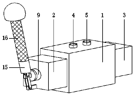
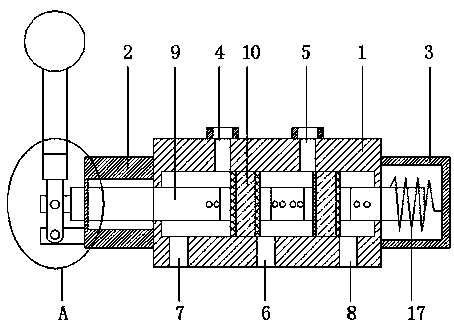
[0002] According to the number of passages controlled by the reversing valve, the hydraulic reversing valve is divided into: two-way, three-way, four-way and five-way, etc., using the relative movement of the spool to adjust the valve body to make the oil flow, shut off or change the oil flow The direction of the hydraulic reversing valve, so that the hydraulic actuator and its driving mechanism can be actuated, terminated or change the direction of motion; the existing hydraulic reversing valve has certain disadvantages in use. The shoulder of the hydraulic reversing valve cannot be disassembled during use, and The type of shoulder should be replaced according to the needs. The shoulder wears a lot after long-term use, resulting in poor sealing of the device, and the handle cannot be disassembled. There are limitations in use, which has a certain impact on the use of the hydraulic reversing valve. For this reason , we propose a reversing hydraulic control valve

Method used


Image

  • Reversing hydraulic control valve
  • Reversing hydraulic control valve
  • Reversing hydraulic control valve

Examples


Embodiment Construction

[0023] In order to make the technical means, creative features, goals and effects achieved by the present invention easy to understand, the present invention will be further described below in conjunction with specific embodiments.

[0024] In the description of the present invention, it should be noted that the terms "upper", "lower", "inner", "outer", "front end", "rear end", "both ends", "one end", "another end" The orientation or positional relationship indicated by etc. is based on the orientation or positional relationship shown in the drawings, and is only for the convenience of describing the present invention and simplifying the description, rather than indicating or implying that the referred device or element must have a specific orientation, use a specific Azimuth configuration and operation, therefore, should not be construed as limiting the invention. In addition, the terms "first" and "second" are used for descriptive purposes only, and should not be understood ...


PUM


Abstract

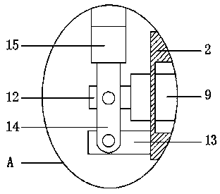
The invention discloses a reversing hydraulic control valve. The reversing hydraulic control valve comprises a valve body and a valve core, a first sealing box is fixedly mounted at one end of the valve body, and a second sealing box is arranged at the other end of the valve body; a first oil hole is formed in one side of the upper end of the valve body, and a second oil hole is formed in one sideof the upper end of the valve body; an oil inlet is formed in the middle position of the lower end of the valve body, a first oil outlet is formed in the portion, one side of the oil inlet, of the lower end of the valve body, and a second oil outlet is formed in the portion, one the other side of the oil inlet, of the lower end of the valve body; a fixing plate is fixedly mounted on the first sealing box, and the valve core is located in the valve body. The reversing hydraulic control valve is provided with detachable shoulder parts, sealing pads and a detachable handle, the shoulder parts different in type are disassembled and replaced, the sealing performance of the interior of the control valve is improved, the detachable handle is convenient to disassemble and store, and a better useprospect is brought.

Description

technical field [0001] The invention relates to the field of hydraulic technology, in particular to a reversing hydraulic control valve. Background technique [0002] The hydraulic reversing valve is divided into two-way, three-way, four-way and five-way according to the number of passages controlled by the reversing valve. direction, so that the hydraulic actuator and its driving mechanism can be driven, terminated or change the direction of motion; the existing hydraulic reversing valve has certain disadvantages in use, and the shoulder of the hydraulic reversing valve cannot be disassembled during use, and The type of shoulder should be replaced according to the needs. The shoulder wears a lot after long-term use, resulting in poor sealing of the device, and the handle cannot be disassembled. There are limitations in use, which has a certain impact on the use of the hydraulic reversing valve. For this reason , we propose a reversing hydraulic control valve. Contents of...

Claims


Application Information

Patent Timeline
IPC IPC(8): F15B13/02F16K11/07F16K3/314F16K27/04F16K31/60F16K3/30
CPCF15B13/02F16K3/30F16K3/314F16K11/0712F16K27/041F16K31/602
Inventor 戚顺平朱志峰苏海燕梁松千
Owner NANTONG AMC MACHINERY
Why Eureka
Try Eureka