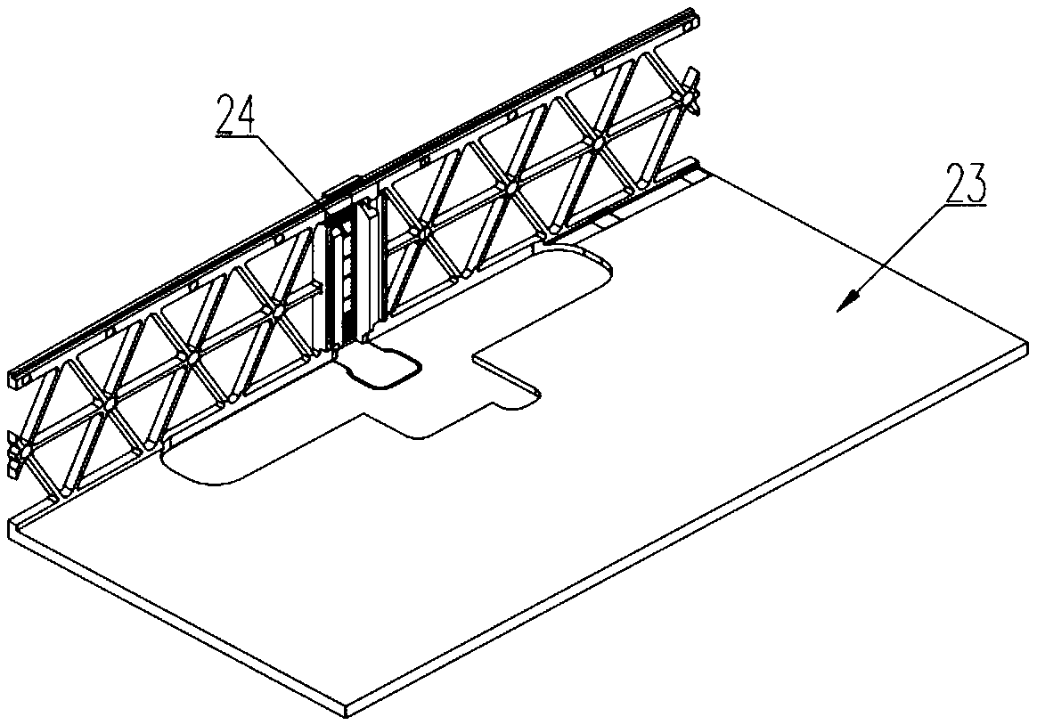
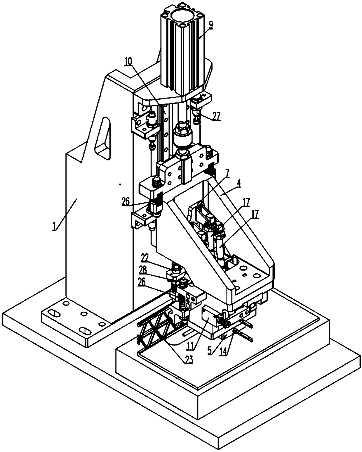
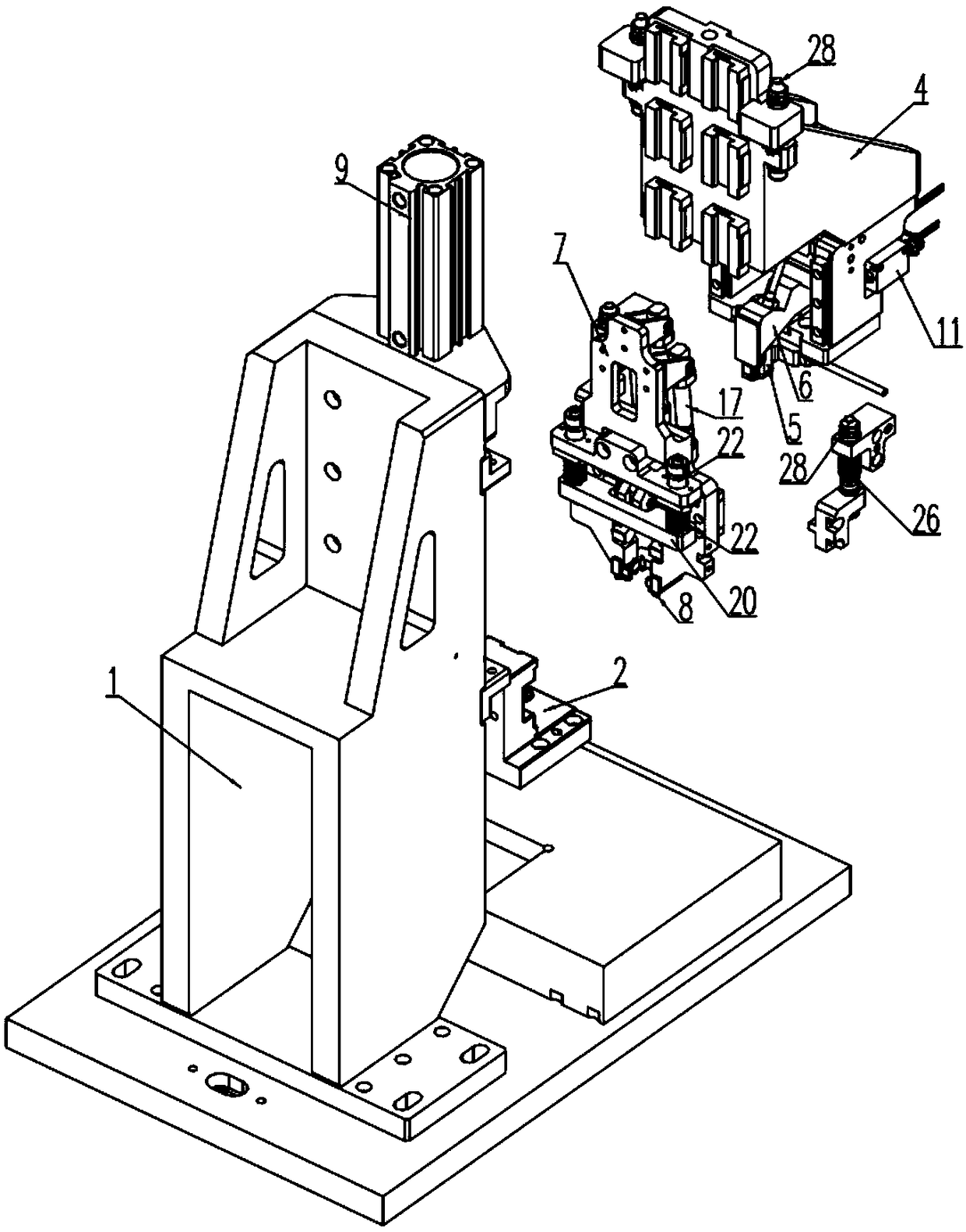
Equipment used for conducting positioning and pressure maintaining on L-shaped part
A technology of parts and pressure holding, which is applied in the field of equipment for positioning and holding L-shaped parts, which can solve the problems of misalignment of L-shaped parts, reduce the risk of parts misalignment, and improve the effect of glue bonding
- Summary
- Abstract
- Description
- Claims
- Application Information
AI Technical Summary
Problems solved by technology
Method used
Image
Examples
Embodiment 1
[0079] like Figure 1 to Figure 10 As shown, it is Embodiment 1 provided by the present invention. This embodiment provides a positioning and pressure maintaining device for positioning and maintaining pressure on two L-shaped parts.
[0080]This embodiment includes a seat body 1, a positioning part 2, a first frame body 4, a first pressing part 5, a second pressing part 6, a second frame body 7, a horizontal segment positioning structure and a vertical segment positioning structure. The positioning member 2 is installed on the base body 1 and has an L-shaped positioning surface, and the L-shaped positioning surface 3 is suitable for positioning the outside of the L-shaped part; the first frame body 4 is vertically arranged on the base body 1, It is suitable for moving up and down driven by the lifting mechanism; the first pressing part 5 is arranged at the lower end of the first frame body 4, and is suitable for moving up and down driven by the first frame body 4. The pressi...
Embodiment approach
[0083] As a specific implementation of the lifting mechanism, the lifting mechanism includes a first power element 9 and a first slide rail 10, the first power element 9 is fixedly installed on the base body 1; the first slide rail 10 is vertically installed on the base body 1 Above; the first frame body 4 is slidably installed on the first slide rail 10 and is suitable for vertical movement along the first slide rail 10 driven by the power element. In this embodiment, the first power element 9 is specifically a telescopic cylinder.
specific Embodiment approach
[0084] As a specific implementation of the translation mechanism, the translation mechanism includes a second power element 11 and a second slide rail 12, the second power element 11 is fixedly installed on the first frame body 4; the second slide rail 12 is horizontally installed on On the first frame body 4; in this embodiment, the second power element 11 is specifically a telescopic cylinder. The second pressing member 6 is slidably installed on the second slide rail 12 and is suitable for sliding along the second slide rail 12 driven by the second power element 11 .
[0085] As a more optimal embodiment of this equipment, between the first frame body 4 and the seat body 1, between the first power element 9 and the first pressing part 5, between the second pressing part Buffer components are installed between 6 and the second power element 11 , and between the first frame body 4 and the second frame body 7 . By installing a buffer member between the above structures, on th...
PUM
 Abstract
Description
Claims
Application Information
 - R&D
- Intellectual Property
- Life Sciences
- Materials
- Tech Scout
- Unparalleled Data Quality
- Higher Quality Content
- 60% Fewer Hallucinations
Browse by: Latest US Patents, China's latest patents, Technical Efficacy Thesaurus, Application Domain, Technology Topic, Popular Technical Reports.
© 2025 PatSnap. All rights reserved.Legal|Privacy policy|Modern Slavery Act Transparency Statement|Sitemap|About US| Contact US: help@patsnap.com


