Electronic equipment detection device

A technology for detection devices and electronic equipment, which is applied to measuring devices, measuring device casings, and parts of electrical measuring instruments, etc., can solve problems such as labor-consuming, inconvenient, and troublesome, and achieve improved usage, convenience, and realization The effect of automation

Inactive Publication Date: 2019-01-18
CHANGZHOU COLLEGE OF INFORMATION TECH
View PDF9 Cites 2 Cited by
  • Summary
  • Abstract
  • Description
  • Claims
  • Application Information

AI Technical Summary

Problems solved by technology

[0002] In the production and manufacturing stage of electronic equipment, due to the differences in the electronic devices that are combined into electronic equipment, the performance of the combined electronic equipment products also has large differences; therefore, performance tests are performed on electronic equipment to ensure the performance of electronic equipment. It is very necessary for quality and performance to meet user requirements; existing electronic equipment testing devices, traditional testing devices, in factory use, due to the relatively large workload of testing electronic products, users use portable devices for testing, which is very It is labor-intensive and very inconvenient, and traditional devices require manual operation, not only manual observation and detection, but also manual adjustment of the machine when facing electronic equipment in different positions, which cannot be realized The automation of the device is very troublesome

Method used


Image

  • Electronic equipment detection device
  • Electronic equipment detection device
  • Electronic equipment detection device

Examples


Embodiment Construction

[0021] The preferred embodiments of the present invention will be described in detail below in conjunction with the accompanying drawings, so that the advantages and features of the present invention can be more easily understood by those skilled in the art, so as to define the protection scope of the present invention more clearly.

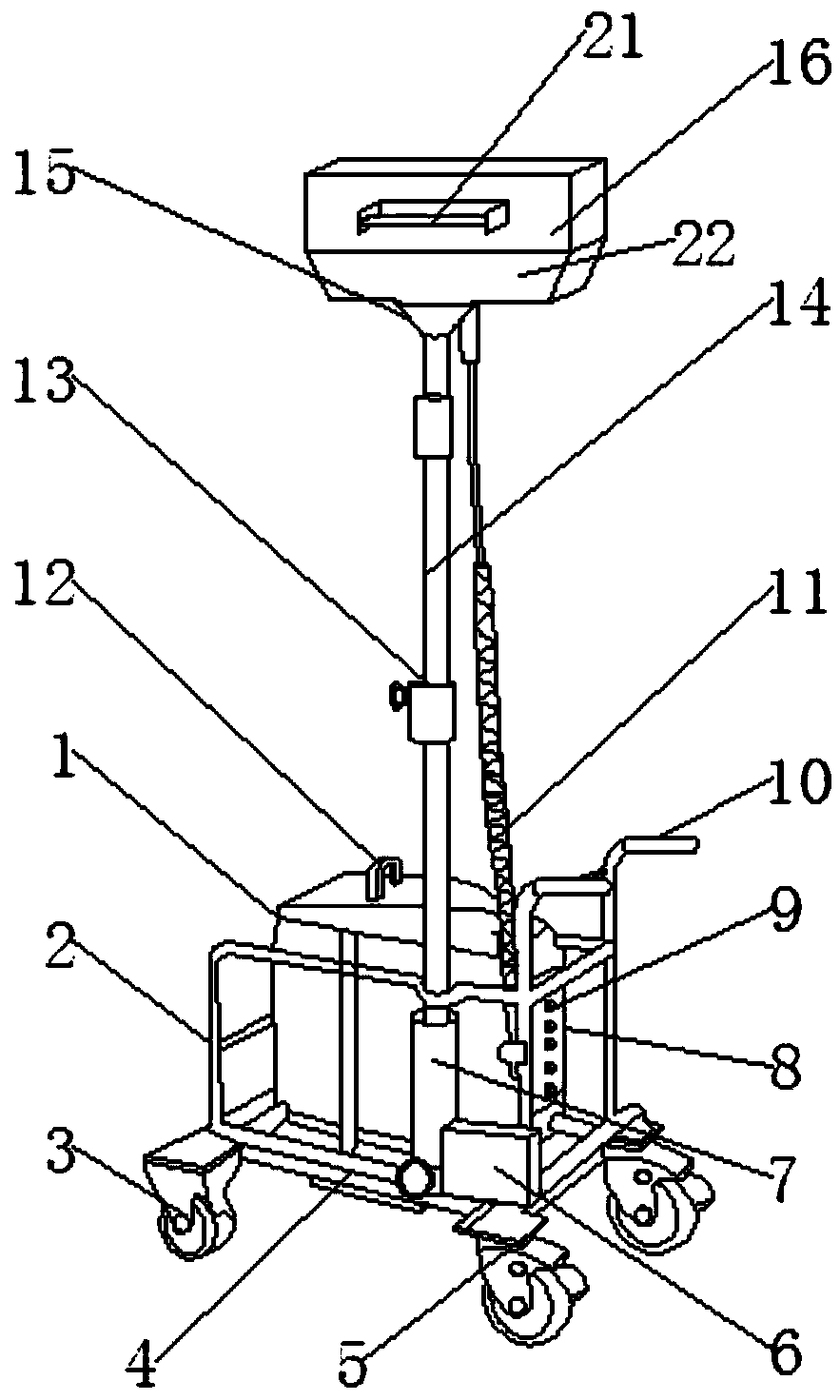
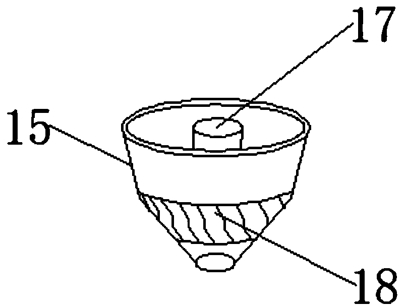
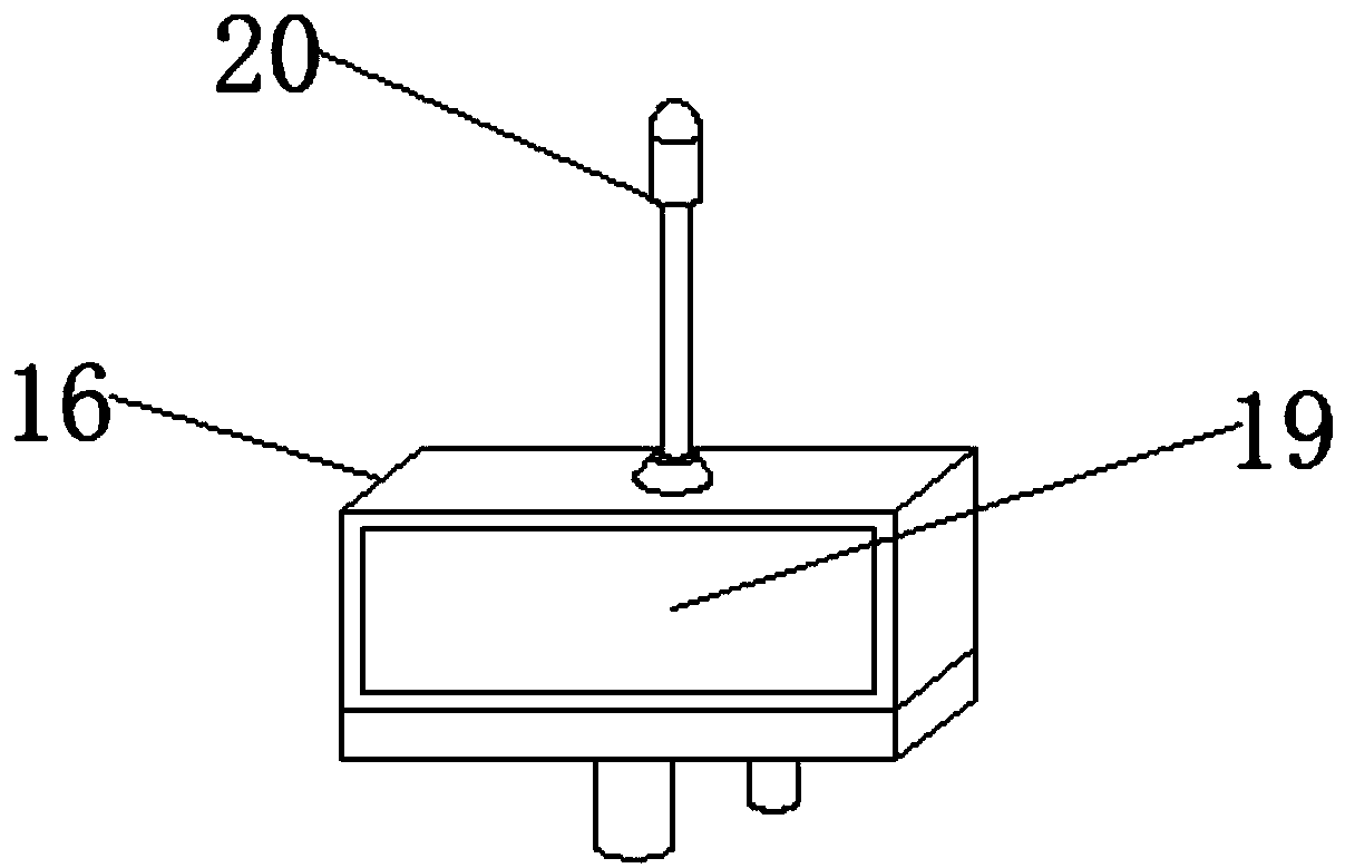
[0022] see Figure 1-3 , the present invention provides a technical solution: an electronic equipment detection device, including a device body 1, a device guardrail 2, a roller 3, a device base 4, a brake pad 5, a hydraulic press 6, a support sleeve 7, a control box 8, and an adjustment button 9 , handle 10, elastic sensing line 11, handle 12, clamp 13, hydraulic telescopic rod 14, universal shaft sleeve 15, detector 16, control shaft 17, rubber sheath 18, detection magnetic sheet 19 and wireless equipment 20. The switch handle 21 and the rotating motor 22, the bottom end of the device body 1 is provided with a device guardrail 2, the bottom end...


PUM


Abstract

The invention discloses an electronic equipment detection device comprising a device body; a device guardrail is arranged at the bottom end of the device body; a device pedestal is arranged at the bottom end of the device guardrail; idler wheels are arranged at all four corners of the bottom end of the device pedestal; a brake pas is arranged at the side end of each idler wheel; a hydraulic machine is arranged at one end of the device pedestal; a support sleeve is arranged on one side of the hydraulic machine; a hydraulic expansion link is arranged at the top end of the support sleeve; a clampis arranged at the middle end of the hydraulic expansion link; a universal shaft sleeve is arranged at the top end of the hydraulic expansion link; a rubber sheath is arranged at the middle end of the universal shaft sleeve. The height of a detector is controlled via the hydraulic machine, and due to the arrangement of the universal shaft sleeve, the shaft sleeve can be folded to a great extent towards each direction due to the rubber sheath at the middle part, and thus a detection device can further adjust the orientation in each direction, and the convenience of the device is greatly improved.

Description

Technical field: [0001] The invention relates to the technical field of electronic equipment detection, in particular to an electronic equipment detection device. Background technique: [0002] In the production and manufacturing stage of electronic equipment, due to the differences in the electronic devices that are combined into electronic equipment, the performance of the combined electronic equipment products also has large differences; therefore, performance tests are performed on electronic equipment to ensure the performance of electronic equipment. It is very necessary for the quality and performance to meet the requirements of users; the existing electronic equipment testing devices, traditional testing devices, in factory use, due to the relatively large workload of testing electronic products, users use portable devices for testing, which is very It is labor-intensive and very inconvenient, and traditional devices require manual operation, not only manual observat...

Claims


Application Information

Patent Timeline
IPC IPC(8): G01R31/00G01R1/04
CPCG01R1/04G01R1/0425G01R31/00
Inventor 唐龙
Owner CHANGZHOU COLLEGE OF INFORMATION TECH
Why Eureka
Try Eureka