A method and device for rapid calibration and focus positioning of the focus plane of a microscopic imaging system

A technology of microscopic imaging and calibration methods, applied in microscopes, instruments, optics, etc., can solve the problems of low precision and large error of focusing algorithm, and achieve the effect of reducing cumulative errors, reducing errors, and simplifying the fitting of surface equations

Active Publication Date: 2021-08-27
BEIJING LUSTER LIGHTTECH
View PDF6 Cites 0 Cited by
  • Summary
  • Abstract
  • Description
  • Claims
  • Application Information

AI Technical Summary

Problems solved by technology

[0005] The purpose of this application is to provide a method and device for rapid calibration of the focal plane of a microscopic imaging system, a focus positioning method and a device, so as to solve the problem of low accuracy caused by large errors in existing focus algorithms

Method used


Image

  • A method and device for rapid calibration and focus positioning of the focus plane of a microscopic imaging system
  • A method and device for rapid calibration and focus positioning of the focus plane of a microscopic imaging system
  • A method and device for rapid calibration and focus positioning of the focus plane of a microscopic imaging system

Examples


Embodiment 1

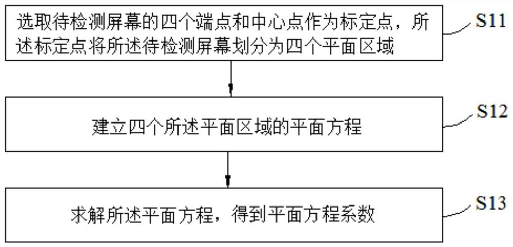
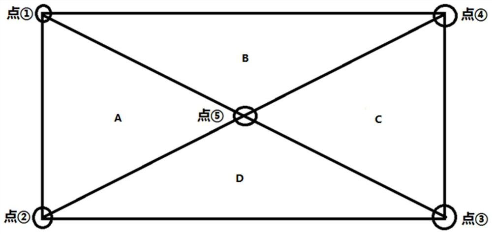
[0088] For the first step, see figure 2 , move the microscopic imaging system so that the center of the field of view of the microscopic imaging system is aligned with the position of the end point ① of the screen to be tested for image acquisition, and a series of image acquisitions are performed according to a fixed pulse interval, and the definition of each image is calculated to make the image clear The position with the highest resolution is used as the focusing surface. If the highest resolution image is in the first or last image, then enlarge the pulse jump range and re-acquire and calculate until convergence (the highest resolution image is not in the first or last image) Zhang), and record the converged coordinates (x_①, y_①, z_①) as the first point of calibration.

[0089] The second step is to move the microscopic imaging system so that the center of the field of view of the microscopic imaging system is aligned with the end point ② of the screen to be tested for ...

Embodiment 2

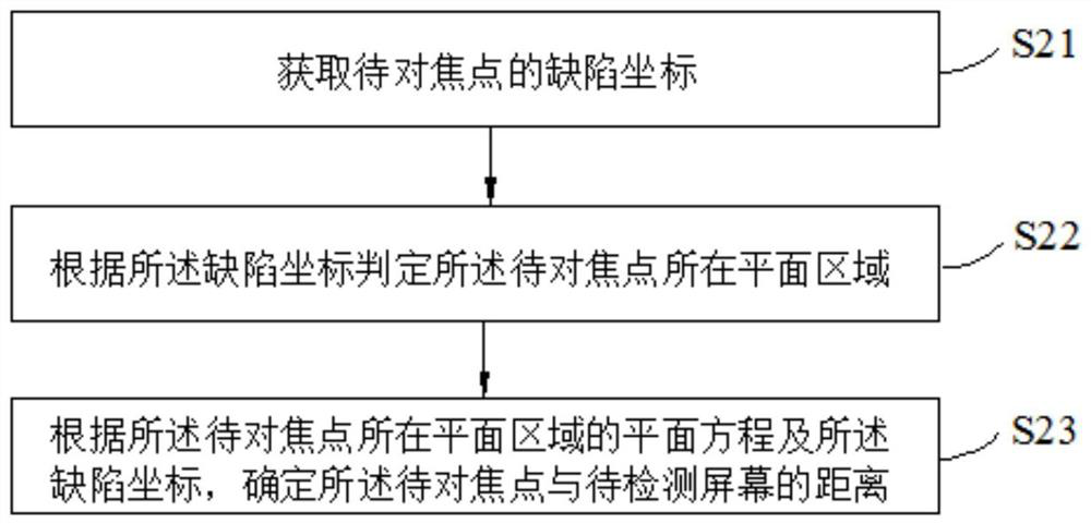
[0107] The first step is to obtain the defect coordinates (x, y) of the point to be focused;

[0108] The second step is to determine which plane area (x, y) the focus point (the point mapped by the center of the field of view of the microscopic imaging system at the imaging position of the mobile phone screen) (x, y) belongs to, for example, it belongs to the A plane area;

[0109] In the third step, according to the plane equation of the plane where the focus point is located and the defect coordinates, that is, the defect coordinates (x, y) are substituted into the plane equation of the A plane area, and the z value is calculated, that is, the distance between the focus point and the defect coordinate is determined. The distance of the screen to be detected.

[0110] It can be seen from the above technical solutions that the embodiment of the present application provides a focus positioning method for a microscopic imaging system, which includes obtaining the defect coordin...


PUM


Abstract

The present application discloses a method and device for rapid calibration and focus positioning of a focus plane of a microscopic imaging system. The calibration method includes selecting four endpoints and a central point of the screen to be detected as calibration points, and the calibration points divide the screen to be detected into four plane areas; establishing plane equations of the four plane areas; solving the plane equations to obtain plane equation coefficients. The focus positioning method includes obtaining defect coordinates of the focus point; determining the plane area where the focus point is located according to the defect coordinates; and determining the distance between the focus point and the screen to be detected according to the plane equation of the plane area where the focus point is located and the defect coordinates. In this application, the screen is divided into four triangular areas, and plane equation fitting is performed respectively to reduce the cumulative error caused by the distance, and the error of each point is minimized due to the triangular plane. This application avoids using the entire mobile phone screen Using the region as a plane leads to very blurred corners that are not involved, and also simplifies the surface equation fitting.

Description

technical field [0001] The present application relates to the technical field of screen defect detection, and in particular to a method for quickly calibrating a focus plane of a microscopic imaging system, a focus positioning method and a device. Background technique [0002] With the continuous development of the liquid crystal display (Liquid Crystal Display, LCD) industry, the automation of liquid crystal screen defect detection equipment is getting higher and higher, and the detection accuracy requirements are getting higher and higher, so the microscopic imaging system has become a must. However, the microscopic imaging system has a small depth of field and high precision, and an error of 1mm may lead to blurred imaging. In order to solve the problem of precision, many kinds of autofocus algorithms have appeared in the industry. [0003] At present, there is a method of using the entire LCD screen area as a plane to fit the plane equation. The main method is to use thr...

Claims


Application Information

Patent Timeline
Patent Type & Authority Patents(China)
IPC IPC(8): G02B21/36
CPCG02B21/365G02B21/368
Inventor 王太兴姚毅解三霞路建伟马增婷
Owner BEIJING LUSTER LIGHTTECH
Why Eureka
Try Eureka