Control system for resonant mixer

A control system and mixing machine technology, applied in general control systems, control/adjustment systems, computer control, etc., can solve the problems of long mixing time and low efficiency, and achieve the effect of fast mixing and uniform, low power consumption

Active Publication Date: 2019-01-18
HUBEI HANGPENG CHEM POWER TECH +1
View PDF6 Cites 1 Cited by
  • Summary
  • Abstract
  • Description
  • Claims
  • Application Information

AI Technical Summary

Problems solved by technology

[0004] The embodiment of the present application proposes a control system for a resonance mixer to solve technical problems such as long mixing time and low efficiency in the prior art

Method used


Image

  • Control system for resonant mixer
  • Control system for resonant mixer
  • Control system for resonant mixer

Examples


Embodiment Construction

[0019] In order to make the technical solutions and advantages of the present application clearer, the exemplary embodiments of the present application will be further described in detail below in conjunction with the accompanying drawings. Obviously, the described embodiments are only part of the embodiments of the present application, not all implementations. Exhaustive list of examples. And in the case of no conflict, the embodiments in this description and the features in the embodiments can be combined with each other.

[0020] Aiming at the deficiencies of the prior art, the embodiment of the present application proposes a control system for a resonance mixer, which will be described below.

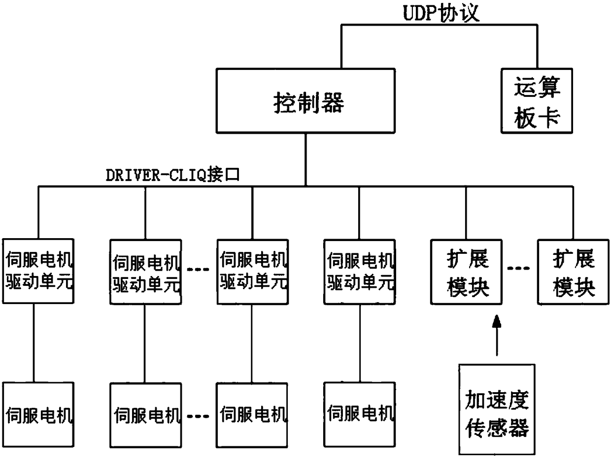
[0021] figure 1 A schematic structural diagram of the control system of the resonance mixer in the embodiment of the present application is shown. As shown in the figure, the control system may include: a controller, an arithmetic board, a servo motor drive unit and an acceleration...


PUM


Abstract

The invention provides a control system for a resonant mixer. The control system comprises a controller, an operation board card, servo motor drive units and an acceleration sensor. The servo motor drive units are connected with servo motors of the resonant mixer. The acceleration sensor is placed at a load end of the resonant mixer. The servo motor drive units are used for sending states and angle values of the servo motors to the controller and controlling the servo motor to rotate according to control signals fed back by the controller. The controller is used for sending the states and angle values of the servo motors sent by the servo motor drive units and load acceleration measured by the acceleration sensor to the operation board card, generating the control signals according to motor angles and acceleration computed by the operation board card and sending the control signals to the servo motor drive units. According to the resonant mixer, in a mode of automatic control and keeping a material in a whole load container at a resonant state, the efficient, rapid and uniform mixing purpose with the lowest power consumption is achieved.

Description

technical field [0001] The present application relates to the technical field of material mixing, in particular to a control system of a resonance mixer. Background technique [0002] Mixing devices are widely used in chemical industry, medicine, battery, cosmetics, ceramics, military industry and other industries to disperse two or more materials to achieve a certain degree of uniformity. Traditional mixing methods include: blending, kneading, kneading, stirring, jet mixing, pipeline mixing, etc. [0003] For the mixing of high-viscosity materials, high-molecular-weight materials, high-value powders, etc., kneading, mixing or stirring devices are commonly used at present. Such mixing devices have the following disadvantages and disadvantages: long mixing time, low efficiency, high energy consumption , Large mixing dead angle, long cleaning time of blades, etc. Due to the long mixing time and high shear force, the mixing of certain high molecular weight materials will also...

Claims


Application Information

Patent Timeline
Patent Type & Authority Applications(China)
IPC IPC(8): G05B19/042
CPCG05B19/0423G05B2219/25257
Inventor 曾庆林王爽张仁杰陆志猛王晨李延林孙涛王青松
Owner HUBEI HANGPENG CHEM POWER TECH
Why Eureka
Try Eureka