

A desktop computer high-efficiency heat dissipation case
A desktop computer, high-efficiency technology, applied in the computer field, can solve the problems of the main chassis cooling effect is not ideal, can not achieve the cooling effect of heat dissipation, etc., to achieve good heat dissipation and exhaust effect, improve the cooling effect, and realize the effect of heat absorption and cooling
- Summary
- Abstract
- Description
- Claims
- Application Information
AI Technical Summary
Problems solved by technology
Method used
Image

Examples
Embodiment 1
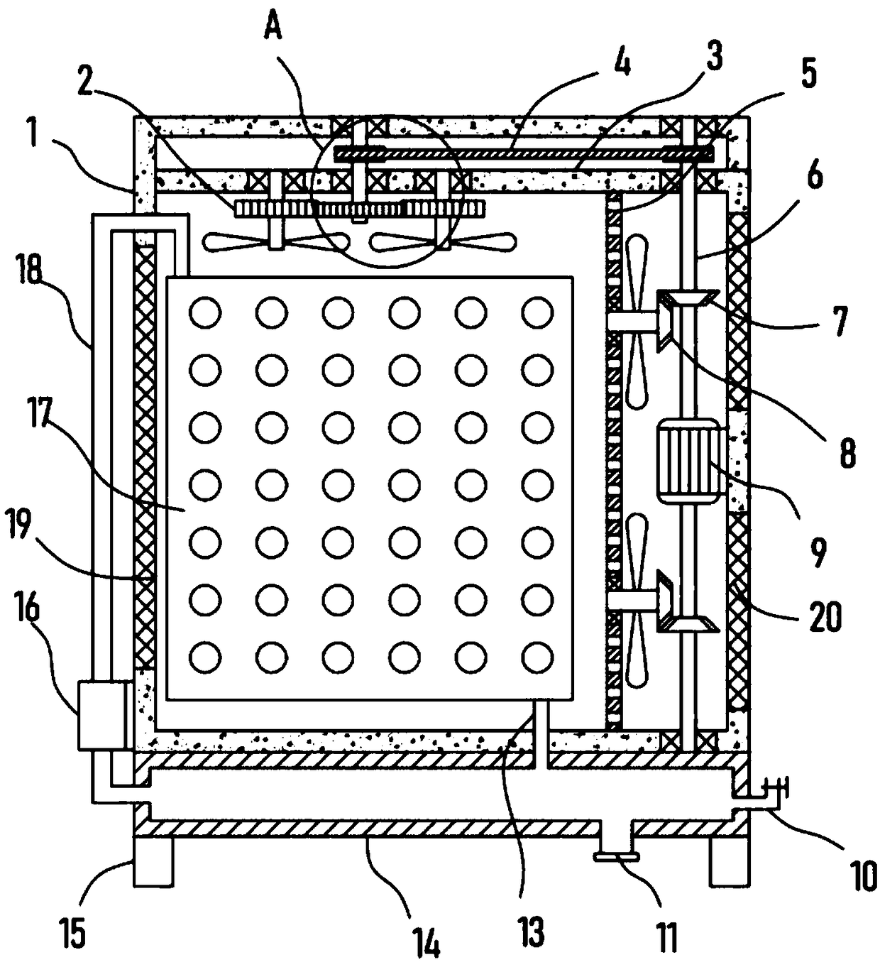
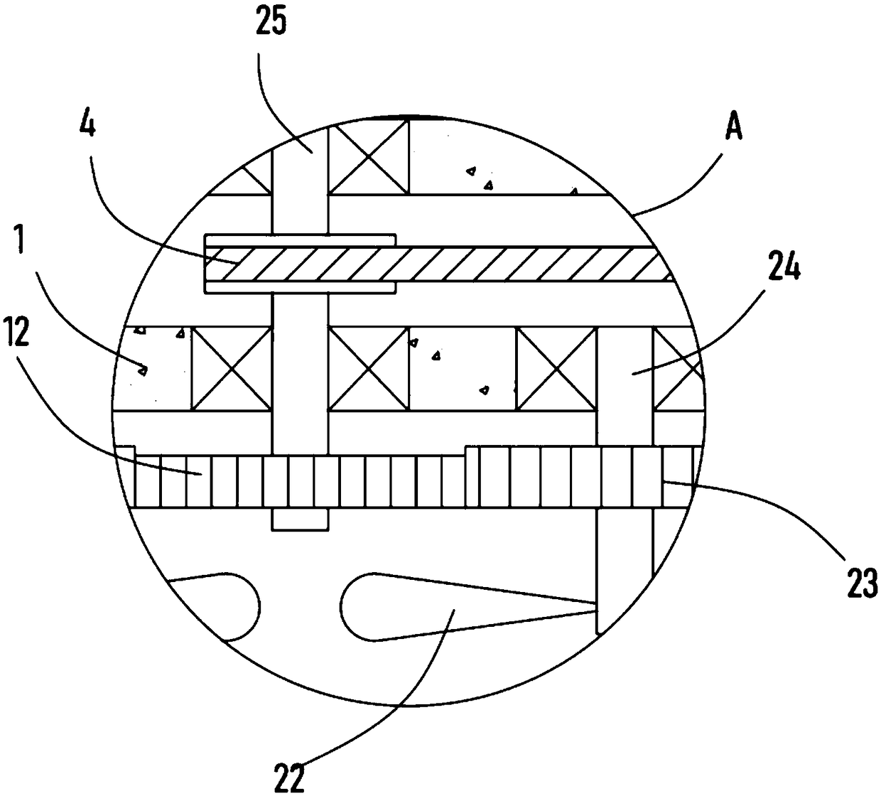
[0021] see Figure 1-3 , a desktop computer high-efficiency heat dissipation chassis, including a main box body 1, a biaxial motor 9 is fixedly installed in the main box body 1, a vertical mesh plate 5 is vertically fixed in the main box body 1, and the vertical mesh plate 5 is rotated The driven shaft is arranged horizontally, the fan blade 22 is fixed on the surface of the driven shaft, the driven bevel gear 8 is coaxially fixed on the driven shaft, the driving shaft of the double-axis motor 9 is coaxially fixed with the driving shaft 6, and the driving shaft 6 A driving bevel gear 7 meshed with a driven bevel gear 8 is fixed on the top.
[0022] The double-axis motor 9 drives the driving shaft 6 to rotate, the driving shaft 6 drives the driving bevel gear 7 to rotate, and the driving bevel gear 7 drives the driven shaft to rotate through the driven bevel gear 8 meshed with it, thereby realizing the fan blade 22 on the driven shaft Rotation to realize the blowing effect on ...
Embodiment 2
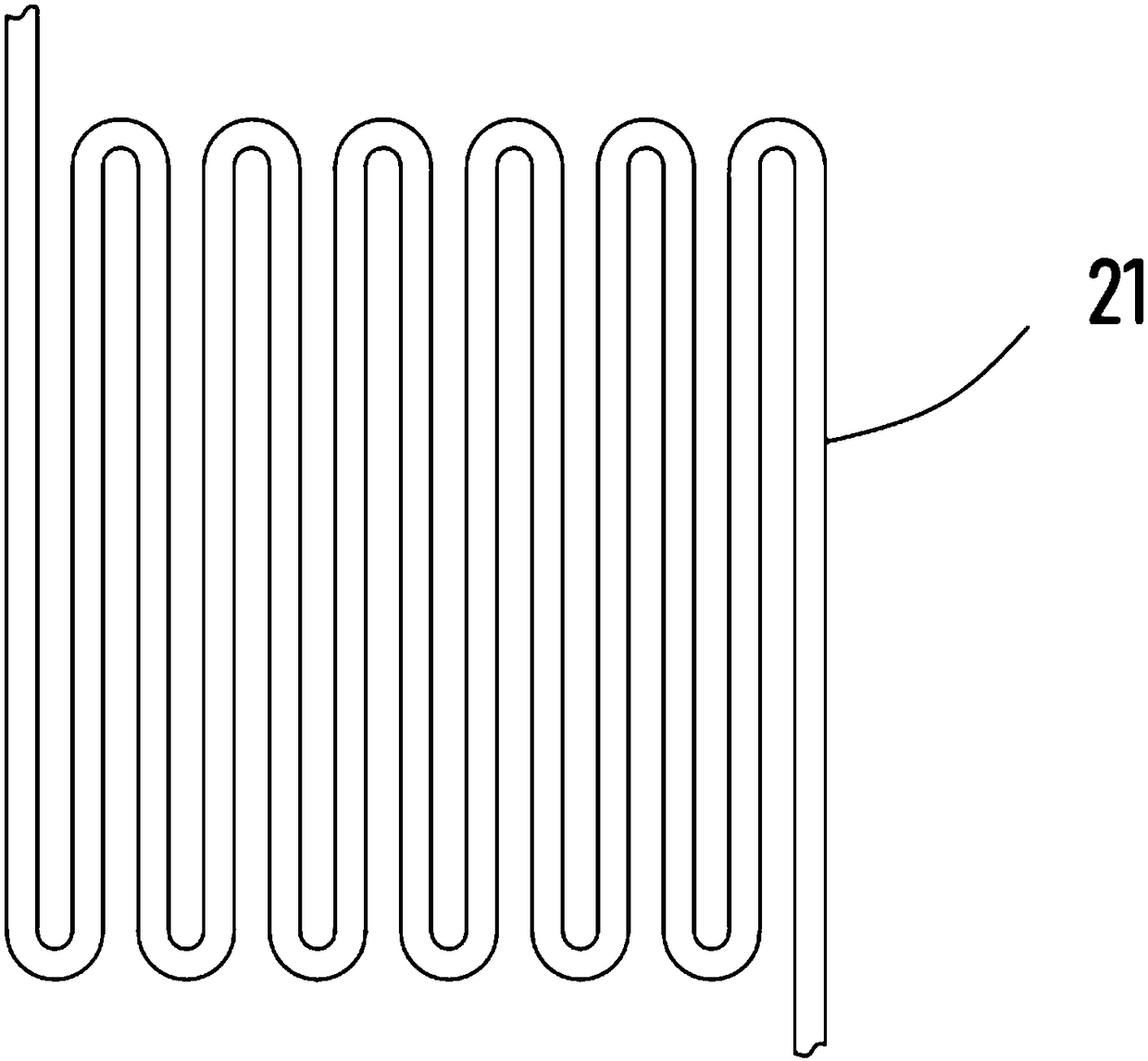
[0027] On the basis of Embodiment 1, in addition, a cold water tank 14 is fixed on the bottom of the main box body 1, and a water pump 16 communicated with the cold water tank 14 through a pipeline is fixed on the main box body 1, and a transmission pipe 18 is installed at the outlet end of the water pump 16. The side wall of the main tank 1 is fixedly installed with a serpentine pipe 21 communicating with the transmission pipe 18 , and the bottom of the serpentine pipe 21 is connected with and installed with a downcomer 13 extending into the cold water tank 14 .
[0028] Further, a liquid inlet pipe 10 is installed on the side wall of the cold water tank 14, and a discharge pipe 11 is vertically installed at the bottom of the cold water tank 14, and ice water can be added to the cold water tank 14 through the liquid inlet pipe 10, and the cold water tank 14 stores the ice water , the ice water in the cold water tank 14 can be transported through the transfer pipe 18 through th...
PUM
 Abstract
Description
Claims
Application Information