Self-circulating magnetic suspension flywheel energy storage generator

A flywheel energy storage and magnetic levitation technology, which is applied in the direction of electrical components, electromechanical devices, electric components, etc., can solve the problems of low transmission efficiency, easy heat generation, and small energy storage, and achieve high transmission efficiency, low heat generation, and low noise.

Pending Publication Date: 2019-01-18
浙江婺舟新能源科技有限公司
View PDF0 Cites 4 Cited by
  • Summary
  • Abstract
  • Description
  • Claims
  • Application Information

AI Technical Summary

Problems solved by technology

[0003] The purpose of the present invention is to provide a flywheel energy storage power generation device that has the disadvantages of small energy storage, low speed, high noise, easy to generate heat, low transmission efficiency, and inability to continuously generate electric energy. Eliminate or reduce the noise, heat and other phenomena during the operation of the flywheel power generation machinery, greatly increase the flywheel speed and reduce friction, improve the working efficiency of the power generation machinery, and realize the self-circulating magnetic levitation flywheel energy storage generator that generates electric energy without interruption

Method used


Image

  • Self-circulating magnetic suspension flywheel energy storage generator
  • Self-circulating magnetic suspension flywheel energy storage generator
  • Self-circulating magnetic suspension flywheel energy storage generator

Examples


Embodiment Construction

[0014] The present invention will be further described through the embodiments below with reference to the accompanying drawings.

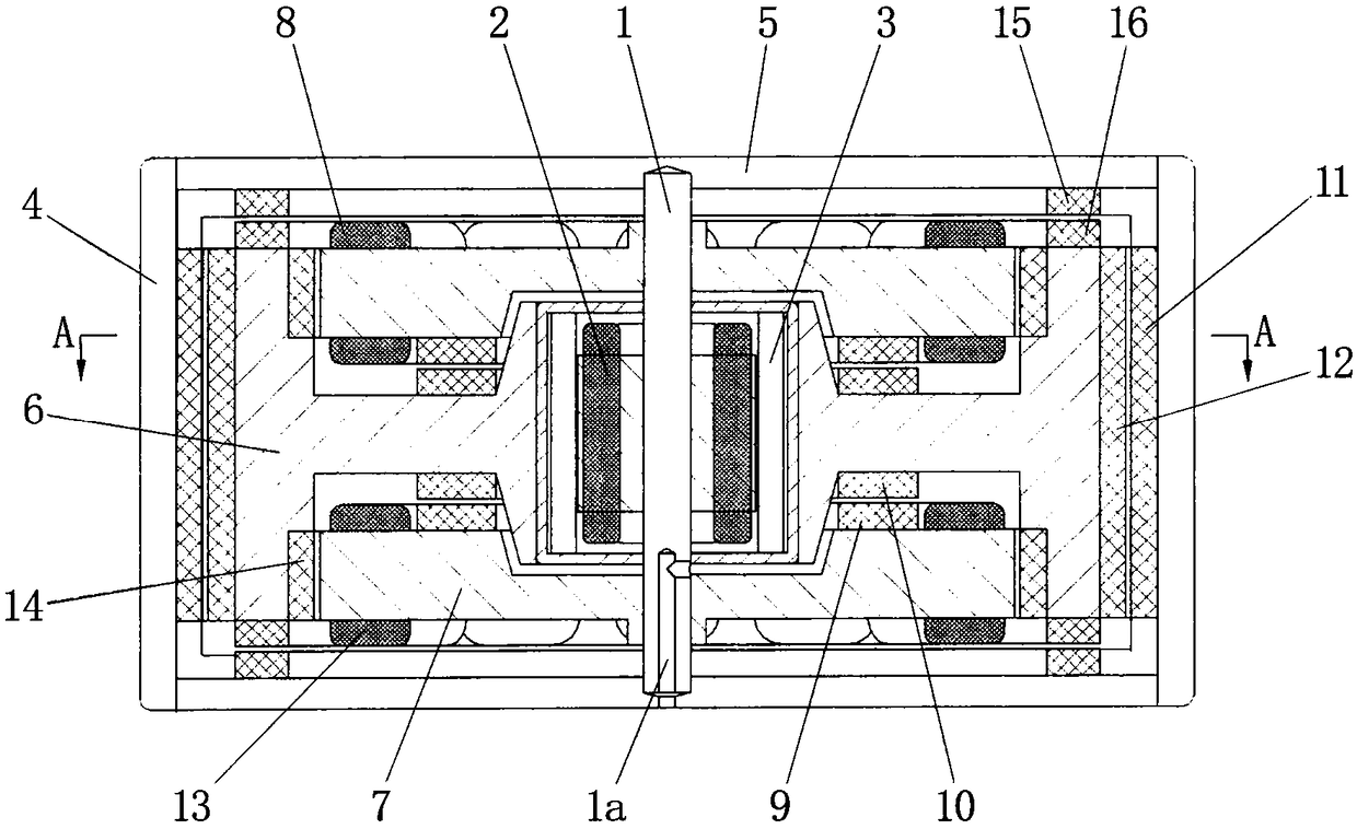
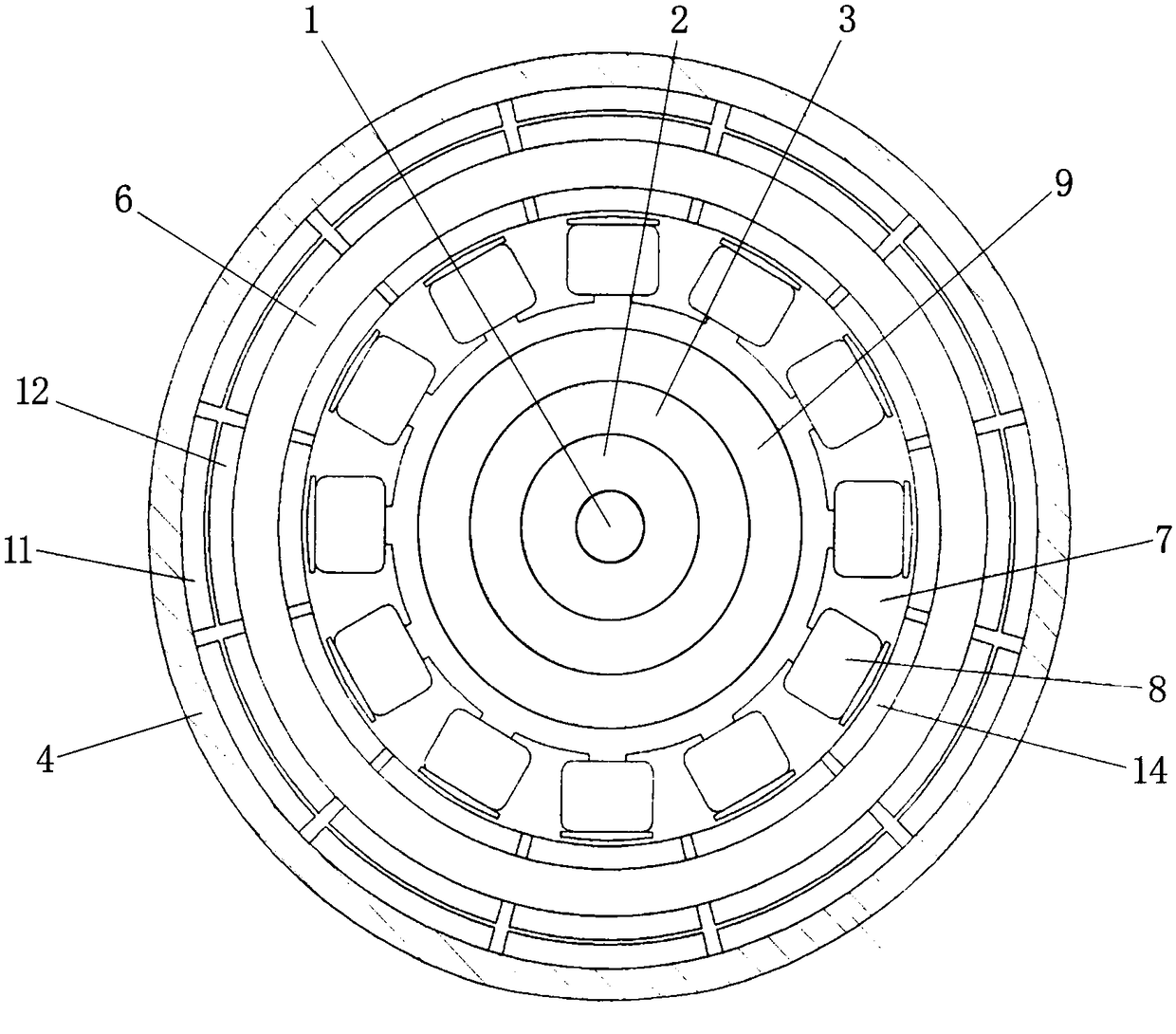
[0015] Refer to attached figure 1 And attached figure 2 A self-circulating magnetic levitation flywheel energy storage generator includes a housing, a drive mechanism, a magnetic levitation structure, an iron core 7, an output coil 8, a self-circulating coil 13 and a rotor 14, wherein:

[0016] The housing includes a shell 4, an end cover 5 and a central shaft 1, the end cover 5 is mounted on the shell 4, the central shaft 1 is mounted on the end cover 5, the The central axis 1 is provided with a through hole 1a for passing through the wire;

[0017] The drive mechanism includes a drive mechanism stator 2, a drive mechanism rotor 3 and a flywheel 6. The drive mechanism stator 2 is in the shape of a hollow shaft. The drive mechanism stator 2 includes a drive mechanism iron core and a drive mechanism coil. The iron core of the driving mechanism ...


PUM


Abstract

The invention belongs to the technical field of power supply and power generation, in particular to a self-circulating magnetic suspension flywheel energy storage generator. The invention aims at thesmall energy storage, low speed and high noise, easy to heat, low transmission benefit existing in the existing flywheel energy storage power generation device, , The invention provides a self-circulating magnetic levitation flywheel energy storage generator which can eliminate or reduce the noise, heat and other phenomena when the flywheel power generation machine is running, greatly increase theflywheel speed and reduce the friction force, improve the working efficiency of the power generation machine, and realize the self-circulating magnetic levitation flywheel energy storage generator which can continuously generate electric energy. The invention comprises a housing, a driving mechanism, a magnetic levitation structure, an iron core, an output coil, a self-circulating coil and a rotor, wherein the driving mechanism comprises a driving mechanism stator, a driving mechanism rotor and a flywheel, and the flywheel is suspended by the magnetic levitation structure. The invention has the characteristics of large energy storage, high rotational speed, low noise, not easy to heat, high transmission efficiency and continuous generation of electric energy.

Description

technical field [0001] The invention belongs to the technical field of power supply and power generation, in particular to a self-circulating magnetic levitation flywheel energy storage generator. Background technique [0002] Various existing flywheel energy storage power generation devices have the following disadvantages: First, small energy storage, low speed, high noise, easy to generate heat, and low transmission efficiency. The reason is that the flywheel and the shaft are matched together by rolling bearings , when the flywheel rotates, there will be frictional resistance due to the direct contact between the surface of the object and the surface of the object, so the above-mentioned drawbacks will occur when the flywheel rotates; Drive the operation mode of one machine with two functions. When running, you need to input external energy first, reverse the power generation machine to drive the machine to accelerate the flywheel, and after the flywheel reaches the pred...

Claims


Application Information

Patent Timeline
Patent Type & Authority Applications(China)
IPC IPC(8): H02K7/02H02N15/00
CPCH02K7/025H02N15/00Y02E60/16
Inventor 杨建荣郭舟林
Owner 浙江婺舟新能源科技有限公司
Why Eureka
Try Eureka