
Camera module control method and device

The technology of a camera module and a control method, which is applied in the electronic field, can solve the problems of increasing the proportion of the screen in the installation space, and achieve the effects of high flexibility and practicability, reducing loss, and avoiding multiple operations

Active Publication Date: 2019-01-18
GUANGDONG OPPO MOBILE TELECOMM CORP LTD
View PDF8 Cites 11 Cited by
  • Summary
  • Abstract
  • Description
  • Claims
  • Application Information

AI Technical Summary

Problems solved by technology

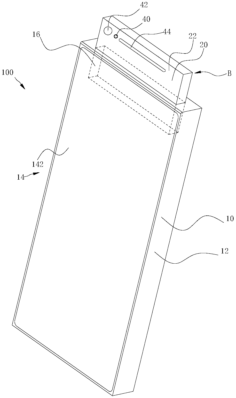
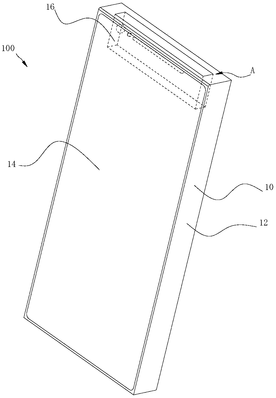
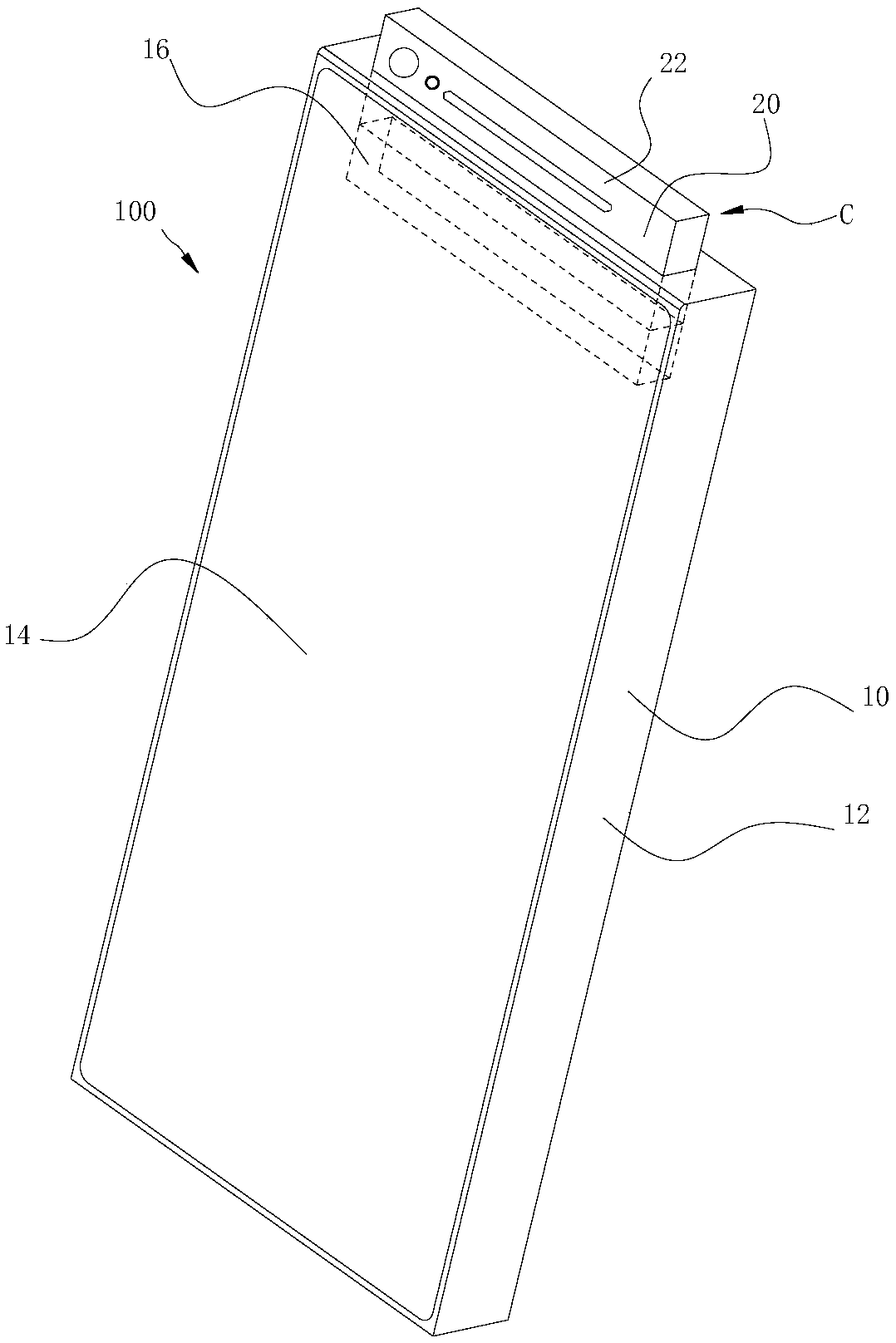
[0003] In related technologies, a camera module and other equipment are installed on the front panel of the electronic device to provide users with front camera services. Therefore, the contradiction between the occupation of the installation space of the camera module on the front panel and the improvement of the screen ratio needs to be resolved urgently.

Method used


Image

  • Camera module control method and device
  • Camera module control method and device
  • Camera module control method and device

Examples


Embodiment Construction

[0026] Embodiments of the present invention are described in detail below, examples of which are shown in the drawings, wherein the same or similar reference numerals designate the same or similar elements or elements having the same or similar functions throughout. The embodiments described below by referring to the figures are exemplary and are intended to explain the present invention and should not be construed as limiting the present invention.

[0027] In describing the present invention, it should be understood that the terms "center", "longitudinal", "transverse", "length", "width", "thickness", "upper", "lower", "front", " Orientation indicated by rear, left, right, vertical, horizontal, top, bottom, inside, outside, clockwise, counterclockwise, etc. The positional relationship is based on the orientation or positional relationship shown in the drawings, which is only for the convenience of describing the present invention and simplifying the description, rather than ...


PUM


Abstract

The invention provides a camera module control method and device, wherein the method comprises the following steps: after receiving a face recognition request sent by a face recognition application, controlling a driving component to drive a sliding component to drive the image pickup module to slide out to a second position; after acquiring the release request of the face recognition applicationto the image pickup module, according to the preset delay strategy, sending a delay retraction instruction delaying the preset time length to the driving component to maintain the sliding component inthe second position within the preset time length; at a preset time, detecting whether that face recognition request is acquire, and if the face recognition request is not acquired, controlling the driving component to drive the sliding component to drive the image pickup module to slide into the first position. Thus, the sliding component reduces the influence of the related component on the screen occupancy, reduces the loss of the related component, and improves the application flexibility of the sliding component.

Description

technical field [0001] The invention relates to the field of electronic technology, in particular to a camera module control method and device. Background technique [0002] With the popularity of portable electronic devices such as smart phones, the optimization of the aesthetics and functionality of electronic devices has become a major trend. For example, the increase in screen ratio of electronic devices is one of the popular trends. [0003] In related technologies, a camera module and other equipment are installed on the front panel of the electronic device to provide users with front camera services. Therefore, the contradiction between the occupation of the installation space of the camera module on the front panel and the improvement of the screen ratio needs to be resolved urgently. . Contents of the invention [0004] The present invention aims to solve one of the technical problems in the related art at least to a certain extent. [0005] Therefore, the prese...

Claims


Application Information

Patent Timeline
IPC IPC(8): H04N5/232G06F21/32
CPCG06F21/32H04N23/611H04M1/0264H04M1/0237H04M2250/52H04M1/72454H04N23/695
Inventor 钟朋
Owner GUANGDONG OPPO MOBILE TELECOMM CORP LTD
Learn More