Device fault location method based on 3D virtual simulation and video monitoring linkage

A technology for video surveillance and equipment failure, applied in the direction of television, closed-circuit television system, registration/indication of machine work, etc., can solve the problems of economic loss of enterprises, inability to understand the operation status and production parameters of production equipment, and multiple routes, etc. Improve maintenance efficiency, reduce troubleshooting time, and reduce economic losses for enterprises

Inactive Publication Date: 2019-01-18
GUANGDONG POWER GRID CO LTD +1
View PDF4 Cites 12 Cited by
  • Summary
  • Abstract
  • Description
  • Claims
  • Application Information

AI Technical Summary

Problems solved by technology

As an important part of industrial automation, the industrial automation production line has always been a major difficulty in factory monitoring because of its many conveying units, complex control mechanisms, large amount of interactive data, many route branches, and large changes. The troubleshooting process after the failure is often time-consuming and long-term, which will cause huge economic losses to the enterprise
[0003] The traditional automatic production line monitoring method is limited to video monitoring, only the appearance of the production equipment can be observed through the video screen, and the operating status and production parameters of the production equipment cannot be understood. When equipment failure occurs, relevant personnel often cannot judge the fault through the video screen point and severity of the fault, it is difficult to accurately locate the faulty device, and it is impossible to find the cause of the fault

Method used


Image

  • Device fault location method based on 3D virtual simulation and video monitoring linkage
  • Device fault location method based on 3D virtual simulation and video monitoring linkage
  • Device fault location method based on 3D virtual simulation and video monitoring linkage

Examples


Embodiment Construction

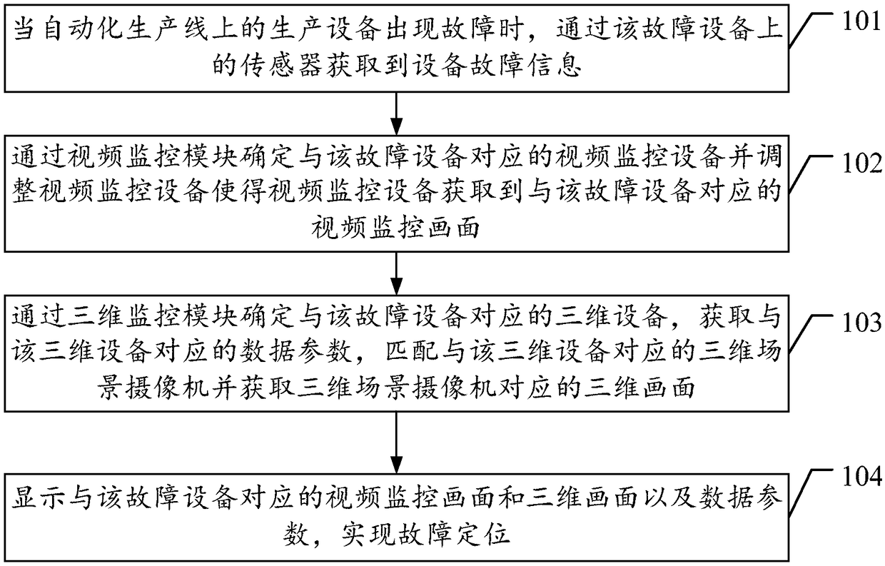
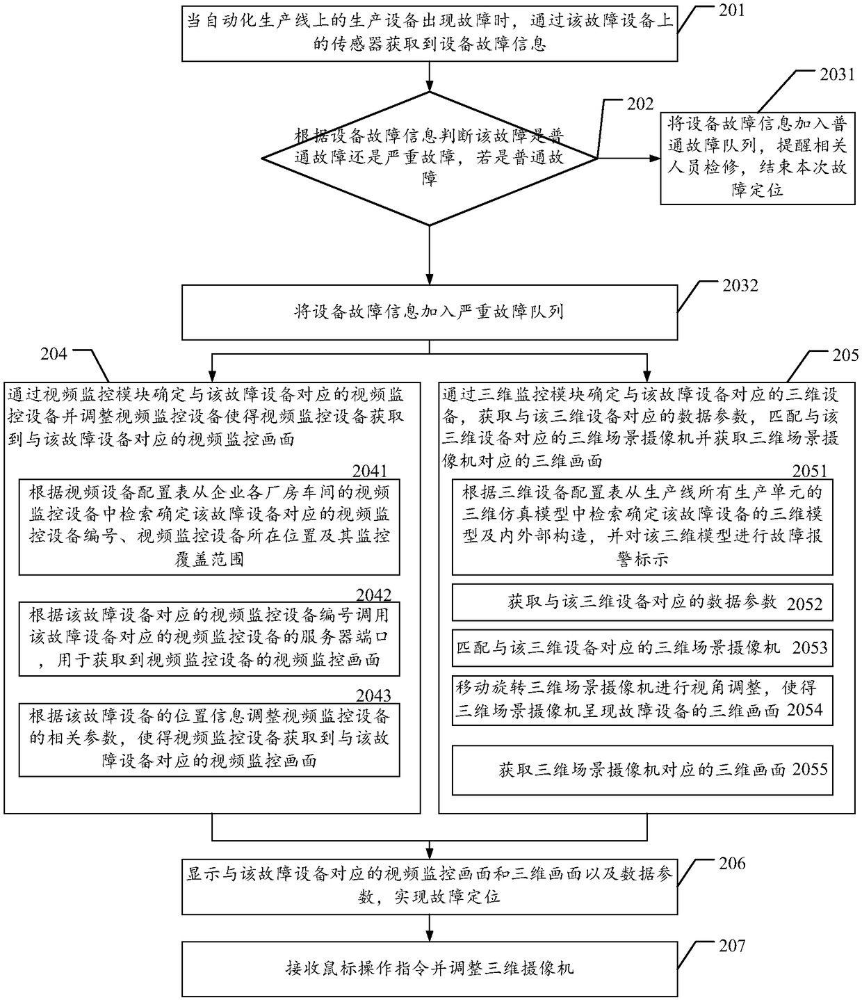
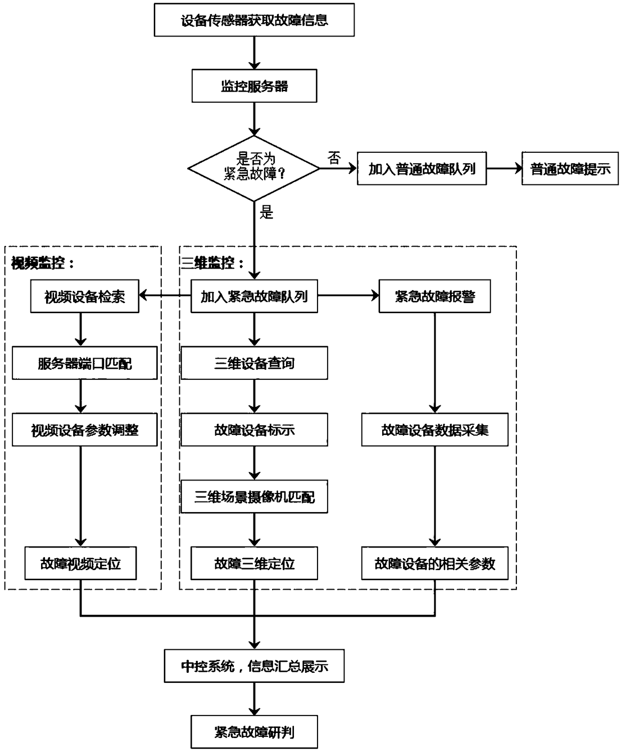
[0050] The invention provides an equipment fault location method based on the linkage of three-dimensional virtual simulation and video monitoring, which can quickly alarm and locate, evaluate the severity of the fault, and analyze the cause of the fault of the production line equipment.

[0051] In order to make the purpose, features and advantages of the present invention more obvious and understandable, the technical solutions in the embodiments of the present invention will be clearly and completely described below in conjunction with the accompanying drawings in the embodiments of the present invention. Obviously, the following The described embodiments are only some, not all, embodiments of the present invention. Based on the embodiments of the present invention, all other embodiments obtained by persons of ordinary skill in the art without making creative efforts belong to the protection scope of the present invention.

[0052] see figure 1 , the present application prov...


PUM


Abstract

The invention provides a device fault location method based on 3D virtual simulation and video monitoring linkage. Through building a multi-dimensional linkage mode of a three-dimensional simulation image, a video signal and fault data for a production unit and combining the three-dimensional virtual simulation and video monitoring, the method can achieve the fault-simulation-video linkage positioning and deep data presentation. When a fault happens, a central control system will instantly give an alarm and indicates a fault device and an alarm condition, and simultaneously switches a monitoring image to the fault position of a workshop. Through the combination of a video image of the onsite scene with the free and flexible browsing and deep data presentation of the three-dimensional monitoring, a user can quickly locate the fault, visually understands the onsite environment and operation parameters of the fault device deeply, estimates the severity of the fault based on the real-timedata and analyzes the cause of the fault, thereby greatly reducing the fault checking time, improving the maintenance efficiency, and reducing the economic loss of an enterprise. The invention also provides a corresponding system.

Description

technical field [0001] The invention relates to the technical field of fault location, in particular to an equipment fault location method based on three-dimensional virtual simulation and video monitoring linkage. Background technique [0002] In recent years, with the widespread application of factory automation, people have higher and higher requirements for remote monitoring and management systems. The 3D virtual simulation monitoring system developed based on data-driven and simulation technology is gradually applied to the actual production of factories. As an important part of industrial automation, the industrial automation production line has always been a major difficulty in factory monitoring because of its many conveying units, complex control mechanisms, large amount of interactive data, many route branches, and large changes. The troubleshooting process after the failure is often time-consuming and long, which will cause huge economic losses to the enterprise. ...

Claims


Application Information

Patent Timeline
Patent Type & Authority Applications(China)
IPC IPC(8): H04N7/18H04N13/204H04N13/296G08B21/18G07C3/00G06Q50/04
CPCG06Q50/04G07C3/005G08B21/18H04N7/181Y02P90/30
Inventor 张永旺党三磊彭策林佳林国营谭跃凯陈亮唐捷黄友朋郑冲
Owner GUANGDONG POWER GRID CO LTD
Why Eureka
Try Eureka