Thrombus removing device system

A thrombus and push rod technology, applied in the field of thrombus retrieval system, can solve the problems of blood vessel injury, brain injury, long time for thrombus removal, etc.

Pending Publication Date: 2019-01-22
SHANGHAI HEARTCARE MEDICAL TECH CORP LTD
View PDF0 Cites 9 Cited by
  • Summary
  • Abstract
  • Description
  • Claims
  • Application Information

AI Technical Summary

Problems solved by technology

However, the existing thrombus retrievers are mainly aimed at thicker blood vessels and cannot access thinner cerebral arteries
And if the thrombectomy stent itself is improperly designed, it is easy to cause irreversible damage to the blood vessel, resulting in restenosis, vascular rupture and other complications; in addition, it is easy to cause the thrombus to fall off during the thrombus grasping process, which is time-consuming and has a low rate of vascular recanalization
If it takes a long time, it will lead to too long ischemic time and easy to cause irreversible damage to the brain
Poor visualization of the thrombectomy stent will also lead to problems such as excessive thrombectomy time, thrombus shedding, and poor thrombolytic effect

Method used


Image

  • Thrombus removing device system
  • Thrombus removing device system
  • Thrombus removing device system

Examples


Embodiment 1

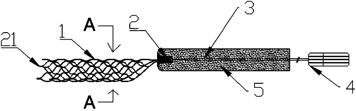
[0104] figure 1 A specific embodiment of the thrombus retriever system involved in the present invention is shown. In this embodiment, the thrombus remover system includes a thrombectomy bracket 1 , a developing ring 2 , a push rod 3 , an introducing sheath 4 and a catcher 5 . The proximal end of the thrombus removal bracket 1 is connected to the distal end of the push rod 3, and a developing ring 2 (belonging to the first type of developing elements 21) is arranged at the connection. The push rod 3 is connected with the introduction sheath 4 . The distal end of the thrombectomy support 1 is provided with a developing element 21 . Both the distal end and the proximal end of the thrombectomy support 1 are open. The proximal end of the thrombectomy bracket 1 is also connected to the catcher 5 .

[0105] The catcher 5 has a first state and a second state. Figure 4A What is shown in is the situation in the first state, the catcher 5 is sleeved outside the push rod 3, and the...

Embodiment 2

[0113] In this embodiment, the distal end and the proximal end of the thrombectomy bracket 1 are provided with developing elements 21, such as Figure 5 shown. There are three developing elements 21 at the distal end, which are evenly distributed on the circumference of the drum-shaped structure of the thrombus retrieval support 1 . In the present invention, evenly distributed on the circumference of the drum-shaped structure of the thrombus retrieval bracket 1 means that the distance between two of them on the circumference is the same or similar. There are one or more developing elements 21 located at the proximal end, and when there are more than one, they are evenly distributed on the circumference of the drum-shaped structure of the thrombus retrieval support 1 . The number of developing elements 21 located at the distal and proximal ends is not limited to Figure 5 As shown, there can be one or more.

Embodiment 3

[0115] In this embodiment, the distal, middle and proximal ends of the thrombectomy bracket 1 are all provided with developing elements 21, such as Figure 6 shown. There are three developing elements 21 at the distal end, which are evenly distributed on the circumference of the drum-shaped structure of the thrombus retrieval support 1 . There are one or more developing elements 21 located in the middle section, and when there are more than one, they are evenly distributed on the circumference of the drum-shaped structure of the thrombus removing support 1 . There are one or more developing elements 21 located at the proximal end, and when there are more than one, they are evenly distributed on the circumference of the drum-shaped structure of the thrombus retrieval support 1 . The number of developing elements 21 located at the distal, middle and proximal ends is not limited to Figure 6 As shown, there can be one or more.


PUM


Abstract

The invention discloses a thrombus removing device system. The thrombus removing device system comprises a thrombus removing bracket, a pushing rod and a capturing part, wherein the near end of the thrombus removing bracket is connected with the pushing rod, and the near end of the thrombus removing bracket or the pushing rod is connected with the capturing part; and the capturing part is arrangedto be capable of storing the thrombus removing bracket. Further, the capturing part comprises a first end and a second end, wherein the first end is connected with the near end of the thrombus removing bracket or the pushing rod; and an opening is arranged in the second end for the thrombus removing bracket and the pushing rod to pass through. The capturing part has a first state and a second state, wherein under the first state, the thrombus removing bracket is positioned outside the capturing part; and under the second state, the capturing part is overturned inwards and outwards for sleeving the thrombus removing bracket inside. For the thrombus removing device system, due to the unique design of the capturing part, the falling thrombus during the thrombus removing process can be effectively captured.

Description

technical field [0001] The invention belongs to the field of medical instruments, in particular to a thrombus retriever system. Background technique [0002] Stroke is currently one of the common diseases in the world, and its characteristics are: high incidence rate, high prevalence rate, and high disability rate. The annual incidence of cerebrovascular disease in my country's urban areas is 219 / 100,000, and that in rural areas is 185 / 100,000, and it is still increasing year by year. From 1998 to 2008, the prevalence of cerebrovascular disease increased from 5.9‰ to 9.7‰. Among the surviving patients with cerebrovascular disease, about three-quarters of them are disabled in different degrees. It is reported that 80% of stroke patients have different degrees of limb dysfunction, and 43.7% of them cannot take care of themselves. Intravenous rt-PA thrombolysis is currently the only effective treatment for acute cerebral infarction proven by evidence-based medicine. However,...

Claims


Application Information

Patent Timeline
Patent Type & Authority Applications(China)
IPC IPC(8): A61B17/22
CPCA61B17/22A61B2017/22038A61B2017/22094
Inventor 刘新峰王国辉王震吴建平薛宗玉周尔辰
Owner SHANGHAI HEARTCARE MEDICAL TECH CORP LTD
Why Eureka
Try Eureka