An auxiliary device for medical imaging in the department of radiology

An auxiliary device and radiology technology, applied in other medical equipment, pharmaceutical equipment, etc., can solve the problems of inconvenient detection, contrast tube falling off, lack of support for contrast tube, etc., and achieve the effect of enhancing practicability

Inactive Publication Date: 2021-03-30
鄂东医疗集团市中医医院
View PDF8 Cites 0 Cited by
  • Summary
  • Abstract
  • Description
  • Claims
  • Application Information

AI Technical Summary

Problems solved by technology

[0004] Aiming at the deficiencies of the prior art, the present invention provides a medical imaging auxiliary device in the radiology department, which solves the problem that the existing imaging tube lacks support. During the struggling process, the contrast tube is easy to fall off, which brings inconvenience to the detection

Method used


Image

  • An auxiliary device for medical imaging in the department of radiology
  • An auxiliary device for medical imaging in the department of radiology
  • An auxiliary device for medical imaging in the department of radiology

Examples


Embodiment 1

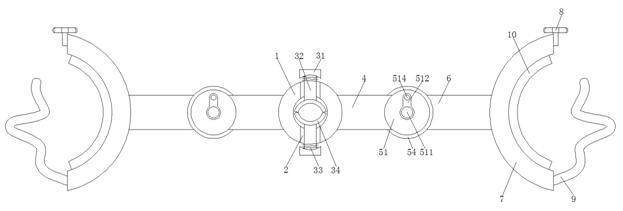
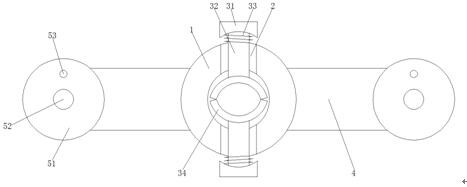
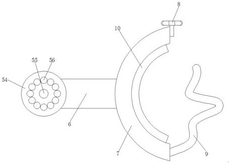
[0030] Such as Figure 1-4 As shown, a radiology medical imaging auxiliary device includes a bearing ring 1, a first opening is symmetrically opened in the center of the top and bottom of the bearing ring 1, a support pad 2 is fixedly connected to the first opening, and the top and bottom of the bearing ring 1 A clamping mechanism 3 is arranged symmetrically in the center, and a first connecting rod 4 is symmetrically fixedly connected to both ends of the bearing ring 1. The end of the first connecting rod 4 far away from the bearing ring 1 is provided with a connecting mechanism 5, and one end of the first connecting rod 4 is arranged There is a second connecting rod 6, and one end of the second connecting rod 6 away from the first connecting rod 4 is fixedly connected with a fixed sleeve 7, one end of the top of the fixed sleeve 7 is fixedly connected with a tightening buckle 8, and one end of the bottom of the fixed sleeve 7 is fixedly connected with a A buffer pad 10 is fi...

Embodiment 2

[0032] On the basis of Embodiment 1, the clamping mechanism 3 includes a clamping cap 31, the center of the clamping cap 31 close to the side of the bearing ring 1 is fixedly connected with a moving rod 32, and the end of the moving rod 32 close to the clamping cap 31 is sleeved with a tension spring 33 , the other end of the moving rod 32 is fixedly connected with a clamping plate 34 .

Embodiment 3

[0034] On the basis of Embodiments 1 and 2, the connecting mechanism 5 includes a first fixed disk 51, the middle of the front of the first fixed disk 51 is provided with a fixing hole 52 communicating with its front and back, and the top of the first fixed disk 51 is provided with a Connect the moving hole 53 of its front and back, the back side of the first fixed disk 51 is provided with the second fixed disk 54, the center of the front of the second fixed disk 54 is provided with a rotation groove 55, and the front of the second fixed disk 54 is provided with a fixed groove 56 , the top and bottom of the inner wall of the fixed hole 52 are symmetrically fixedly connected with fixed blocks 57 on the front and the back, the top and bottom of the inner cavity of the fixed hole 52 are symmetrically provided with clamping plates 58, and the middle of the top and bottom of the inner wall of the moving hole 53 is symmetrically provided with a chute 59. The bottom of the rotating groo...


PUM


Abstract

The invention discloses a medical radiography auxiliary device for the radiology department, and relates to the technical field of medical radiography auxiliary tools for the radiology department. Themedical radiography auxiliary device for the radiology department comprises a bearing ring, wherein first openings are symmetrically formed in the centers of the top and the bottom of the bearing ring, support pads are fixedly connected to the first openings, clamping mechanisms are symmetrically arranged in the centers of the top and the bottom of the bearing ring, first connecting rods are fixedly connected to two ends of the bearing ring symmetrically, connecting mechanisms are arranged at one ends, far away from the bearing ring, of the first connecting rods, second connecting rods are arranged at one ends of the first connecting rods, fixing sleeves are fixedly connected to one ends, far away from the first connecting rods, of the second connecting rods, and fastening buckles are fixedly connected to one ends of the tops of the fixing sleeves. For the medical radiography auxiliary device for the radiology department, while a radiography tube is fixed by utilizing the pushing effect of clamping plates on two sides, the acting force of the clamping plates can not close the radiography tube, and therefore, effective support is provided for the fixing of the radiography tube.

Description

technical field [0001] The invention relates to the technical field of radiology medical radiography auxiliary equipment, in particular to a radiology medical radiography auxiliary device. Background technique [0002] Among the factors of female infertility, tubal obstruction accounts for a large proportion, 30% to 50% according to statistics. The simplest and most effective method for diagnosing tubal obstruction is hysterosalpingography. In addition to traditional gynecological surgery, interventional recanalization is currently carried out in hospitals at all levels because of its simple operation, convenience and effectiveness, and low technical requirements. The catheters used for salpingography are basically commercially available disposable sterile hysterosalpingography catheters. Chinese Patent No. CN103861197A proposes a hysterosalpingography tube, including a contrast tube, an inner support tube, an interventional guide wire and corresponding catheters, which can...

Claims


Application Information

Patent Timeline
Patent Type & Authority Patents(China)
IPC IPC(8): A61M31/00
CPCA61M31/00
Inventor 何顺利熊超刘丹卓军
Owner 鄂东医疗集团市中医医院
Why Eureka
Try Eureka