Deployment and recovery device of a flight suspension type underwater glider

A recovery device and suspension technology, which is applied in the field of flying suspension underwater glider deployment and recovery devices, can solve problems such as the difficulty of avoiding the collision between the glider and the hull, the difficulty of deploying and recovering the glider, and damage to the underwater glider. , to achieve efficient deployment and recovery work, improve deployment and recovery efficiency, and compact structure

Active Publication Date: 2019-01-22
CHINA SHIP SCIENTIFIC RESEARCH CENTER (THE 702 INSTITUTE OF CHINA SHIPBUILDING INDUSTRY CORPORATION)
View PDF5 Cites 2 Cited by
  • Summary
  • Abstract
  • Description
  • Claims
  • Application Information

AI Technical Summary

Problems solved by technology

Due to the influence of wind, waves, and currents on the sea, the mother ship carrying the underwater glider has a large pitch and heel swing during operation, and the shaking is relatively severe. It is difficult to avoid the collision between the glider and the hull. Therefore, the glider There are certain difficulties in deploying and recovering at sea
[0003] At present, the deployment and recovery of underwater glider in China mainly adopts fishing net deployment and recovery, slideway deployment and recovery, fixture deployment and recovery, etc. There are certain requirements. At the same time, the underwater glider is easy to collide with the mother ship when it is recovered, and there is a danger of damaging the underwater glider. It is difficult to realize the rapid deployment and recovery of the underwater glider through the above methods.

Method used


Image

  • Deployment and recovery device of a flight suspension type underwater glider
  • Deployment and recovery device of a flight suspension type underwater glider
  • Deployment and recovery device of a flight suspension type underwater glider

Examples


Embodiment Construction

[0023] The specific implementation manner of the present invention will be described below in conjunction with the accompanying drawings.

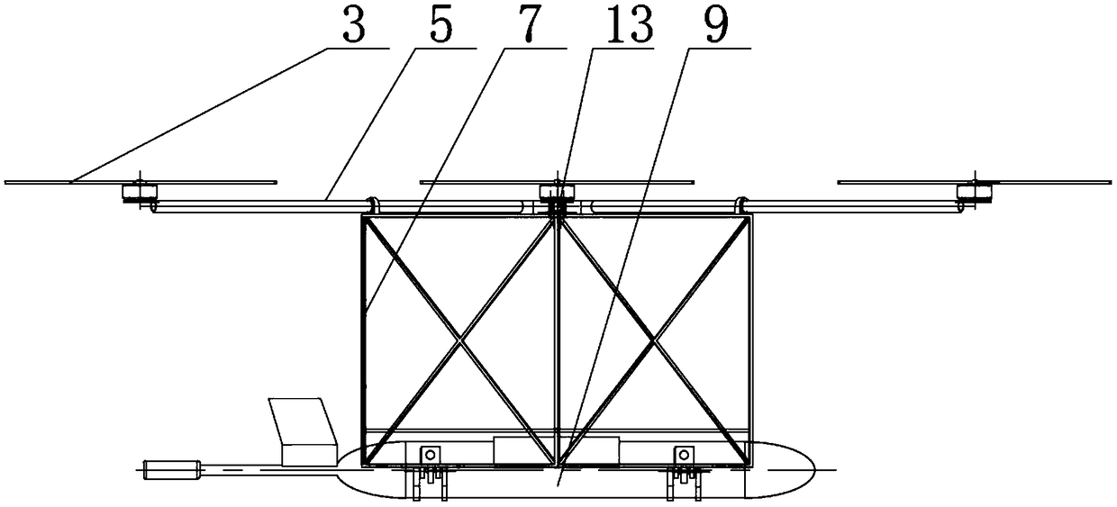
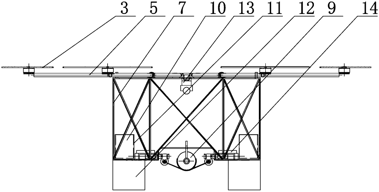
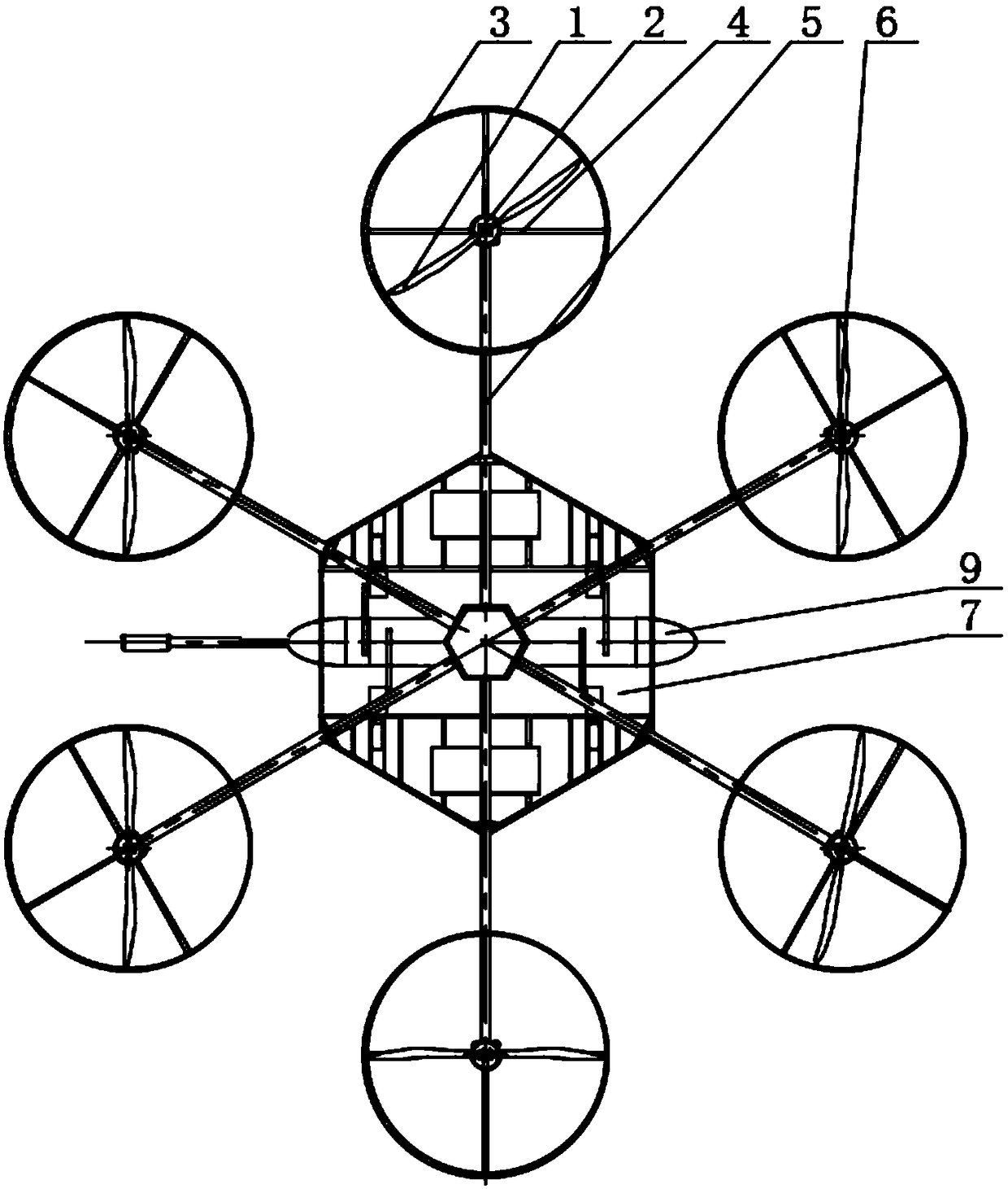
[0024] Such as figure 1 , figure 2 , image 3 and Figure 4 As shown, the flying suspension type underwater glider deployment recovery device of the present embodiment includes a frame 7 with a frame structure, a controller 8 is installed in the middle of the top surface of the frame 7, and a camera is installed below the controller 8. 13. The outer ring of the controller 8 in the circumferential direction is evenly spaced with a plurality of motor folding support frames 5, the head of each motor folding support frame 5 is fixed with a rotating motor 2, and the output end of the rotating motor 2 is equipped with a propeller fixing plate 6 , the propeller 1 is installed on the propeller fixing plate 6, and the head of each motor folding support frame 5 is also fixed with a cross-shaped conduit fixing frame 4, and a circular conduit 3 is...


PUM


Abstract

A deployment and recovery device of a flight suspension type underwater glider comprises a frame structure. A controller is mounted in the middle of the top surface of the rack, a camera is mounted under the controller, a plurality of motor folding brackets are uniformly spaced apart from each other in the circumferential direction of the outer ring of the controller, the head of each electric motor folding support frame is fixed with a rotating electric machine, the output end of the rotating electric machine is installed with a propeller fixing plate, the propeller is installed on the propeller fixing plate, the head of each electric motor folding support frame is also fixed with a cross-shaped conduit fixing frame, and a circular conduit is installed on the outside of the conduit fixingframe; a battery box fixing seat is also installed on the inner side of the rack, a battery is installed on the inner side of the battery box fixing seat, a self-clamping catch device is symmetrically installed on the bottom of the rack, and two self-clamping catch devices grasp the glider; air bags are installed at both ends of the bottom of the frame. The device is flexible and reliable to use.

Description

technical field [0001] The invention relates to the technical field of deploying and recovering devices, in particular to a deploying and recovering device for a flying suspension underwater glider. Background technique [0002] In the process of obtaining test data related to the marine environment for an underwater glider, the first step is to safely deploy the glider from the mother ship into the ocean, and finally safely recover the underwater glider from the sea. The underwater glider is a precision testing device. Its pressure-resistant structure is made of aluminum alloy, and its surface hardness is weak, so it cannot collide with the hull or hard objects. Due to the influence of wind, waves, and currents on the sea, the mother ship carrying the underwater glider has a large pitch and heel swing during operation, and the shaking is relatively severe. It is difficult to avoid the collision between the glider and the hull. Therefore, the glider There are certain diffic...

Claims


Application Information

Patent Timeline
Patent Type & Authority Applications(China)
IPC IPC(8): B63B23/00B63C11/52B60F5/02
CPCB60F5/02B63B23/00B63C11/52
Inventor 徐令令吴宝山张波赵桥生姚木林张华王健李永成
Owner CHINA SHIP SCIENTIFIC RESEARCH CENTER (THE 702 INSTITUTE OF CHINA SHIPBUILDING INDUSTRY CORPORATION)
Why Eureka
Try Eureka