A Passive Matrix Driven Liquid Crystal Display

A liquid crystal display and matrix technology, which is applied in the field of passive matrix drive liquid crystal displays, can solve problems such as cumbersome operation, insufficient locking force of fasteners, and reduced stability of liquid crystal displays, so as to facilitate disassembly, replacement and installation, improve convenience, The effect of improving stability

Active Publication Date: 2020-12-22
山东融通电子科技有限公司
View PDF7 Cites 0 Cited by
  • Summary
  • Abstract
  • Description
  • Claims
  • Application Information

AI Technical Summary

Problems solved by technology

[0004] The invention provides a passive matrix driven liquid crystal display, which has the advantages of good cleaning effect, convenient cleaning and angle adjustment, and solves the problem that the currently used liquid crystal display does not have an automatic cleaning function, and the surface of the liquid crystal display is used for a long time due to electrostatic adsorption. Dust affects the cleanliness and viewing effect of the liquid crystal display, and the angle of the existing liquid crystal display can only be adjusted in the vertical direction. If you want to adjust the angle in the horizontal direction, you need to move the entire liquid crystal display, which is difficult to operate. It is cumbersome, and the fasteners need to be loosened and locked before and after the existing angle adjustment. The wear after long-term use leads to insufficient locking force of the fasteners, which reduces the stability of the LCD display.

Method used


Image

  • A Passive Matrix Driven Liquid Crystal Display
  • A Passive Matrix Driven Liquid Crystal Display
  • A Passive Matrix Driven Liquid Crystal Display

Examples


Embodiment Construction

[0025] The following will clearly and completely describe the technical solutions in the embodiments of the present invention with reference to the accompanying drawings in the embodiments of the present invention. Obviously, the described embodiments are only some, not all, embodiments of the present invention. Based on the embodiments of the present invention, all other embodiments obtained by persons of ordinary skill in the art without making creative efforts belong to the protection scope of the present invention.

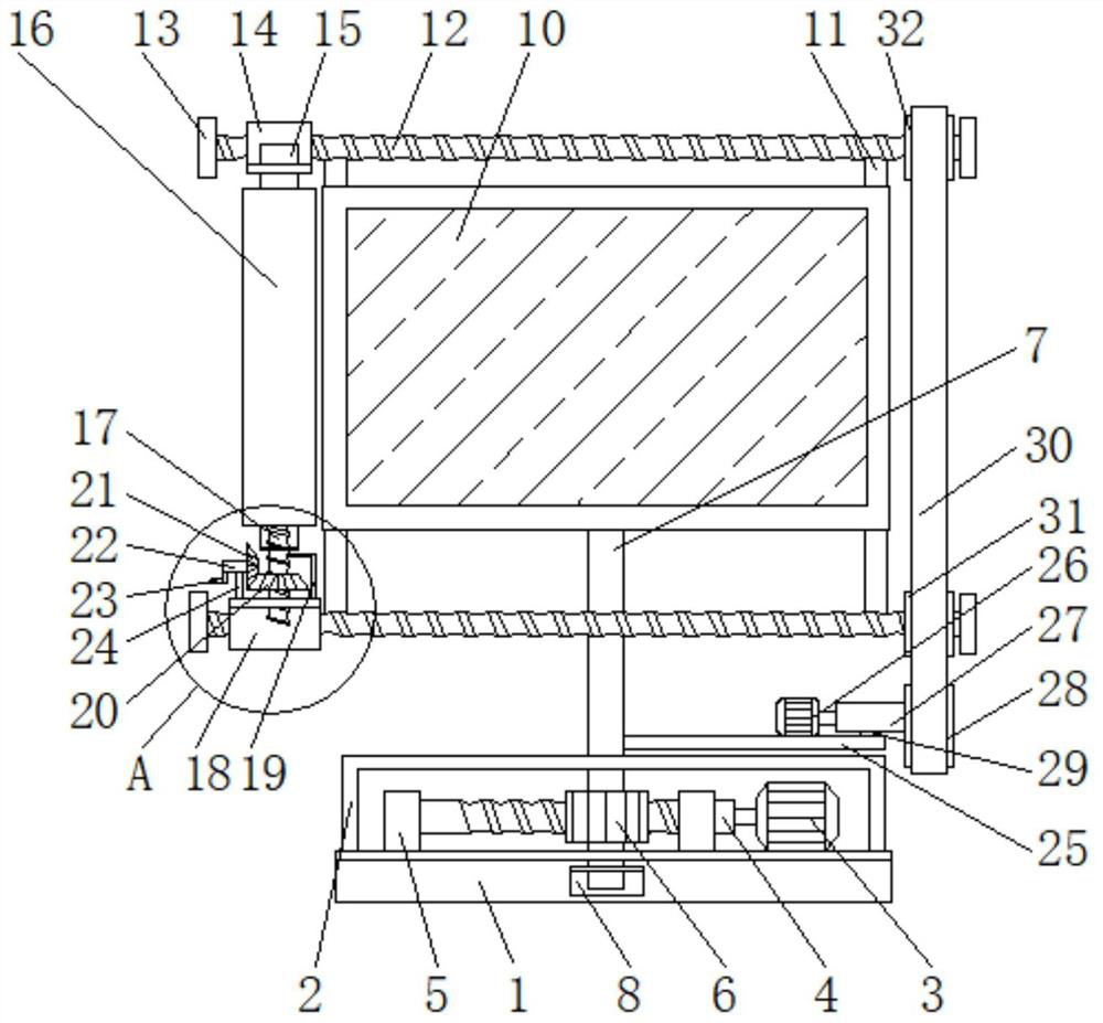
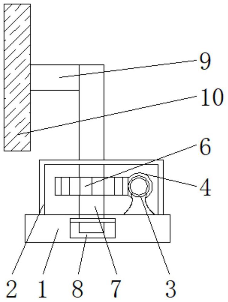
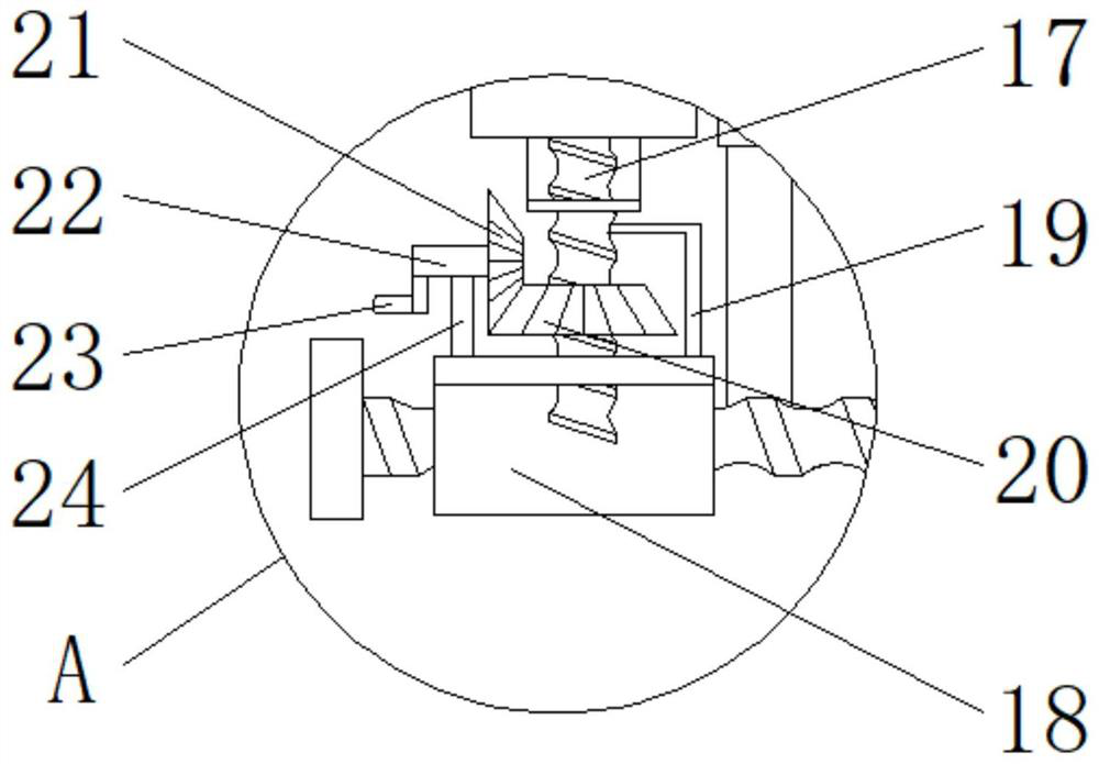
[0026] see Figure 1-6, a passive matrix driven liquid crystal display, comprising a base 1, an adjustment box 2 is fixedly installed on the top of the base 1, and a first motor 3 is fixedly installed at one end of the inside of the adjustment box 2, the model of the first motor 3 is Y90S-4, and The output end of the first motor 3 is fixedly socketed with one end of the worm 4, the worm 4 is located directly behind the worm wheel 6, and the bottom of the worm ...


PUM


Abstract

The invention relates to the technical field of liquid crystal screen display equipment, and discloses a passive matrix driven liquid crystal display. The passive matrix driven liquid crystal displaycomprises a base, wherein an adjusting box is fixedly mounted on the top of the base; a first motor is fixedly mounted at one end of the inside of the adjusting box; the output end of the first motoris fixedly connected with one end of a worm in a sleeving manner; the two ends of the worm are separately connected with the tops of supporting rods I mounted in an adjusting box fixedly in a sleevingmanner; the middle of the worm is engaged with the outside of a worm gear; and the middle of the worm gear is fixedly connected with a supporting rod II in a sleeving manner. According to the passivematrix driven liquid crystal display, by combined action of the worm and the worm gear, the angle of the liquid crystal display is convenient to adjust, demands of people on the passive matrix drivenliquid crystal display at different angles when people watch videos can be met, the practicality of the liquid crystal display is improved, meanwhile, a self-locking function is fulfilled due to engagement of the worm and the worm gear, after being adjusted to a certain angle, the liquid crystal display cannot rotate randomly, and thus, the stability of the liquid crystal display is improved.

Description

technical field [0001] The invention relates to the technical field of liquid crystal display devices, in particular to a passive matrix driven liquid crystal display. Background technique [0002] Liquid crystal display is a kind of flat-panel display, which is used for the screen display of televisions and computers. The advantages of this display are low power consumption, small size, and low radiation. The liquid crystal display uses two polarized materials A liquid crystal solution through which an electric current will rearrange the crystals for imaging purposes. [0003] The currently used liquid crystal display does not have an automatic cleaning function. For long-term use of the liquid crystal display, a large amount of dust is adsorbed on the surface of the liquid crystal display, which affects the cleanliness and viewing effect of the liquid crystal display. Moreover, the angle of the existing liquid crystal display can only be in the vertical direction. If you ...

Claims


Application Information

Patent Timeline
Patent Type & Authority Patents(China)
IPC IPC(8): F16M11/06G09F9/35B08B1/00
CPCB08B1/002F16M11/06G09F9/35
Inventor 不公告发明人
Owner 山东融通电子科技有限公司
Why Eureka
Try Eureka