

Sealing methods for batteries
A battery and battery casing technology, which is applied to batteries, sealing materials, battery pack components, etc., can solve problems such as electrolyte leakage, plate breakage, shortened service life, etc., and achieve good sealing effect
Active Publication Date: 2019-01-22
GUANGZHOU ZHUOYUE POWER NEW ENERGY CO LTD
View PDF13 Cites 1 Cited by
- Summary
- Abstract
- Description
- Claims
- Application Information
AI Technical Summary
Problems solved by technology
At present, most of the batteries adopt the plate pressing type battery, and several plates are pressed and fixed in the battery shell. It is inevitable to bump and vibrate during the driving process of the car. The battery with this structure is easy to be bumped and vibrated during long-term use. Part of the plate is broken, and the electrolyte is prone to leakage, which affects the input and output of the battery and shortens its service life
Method used
View moreImage
Smart ImageViewing Examples

Examples
Embodiment Construction
[0021] The present invention will be described in further detail below by means of specific embodiments:
Login to View More PUM
 Abstract
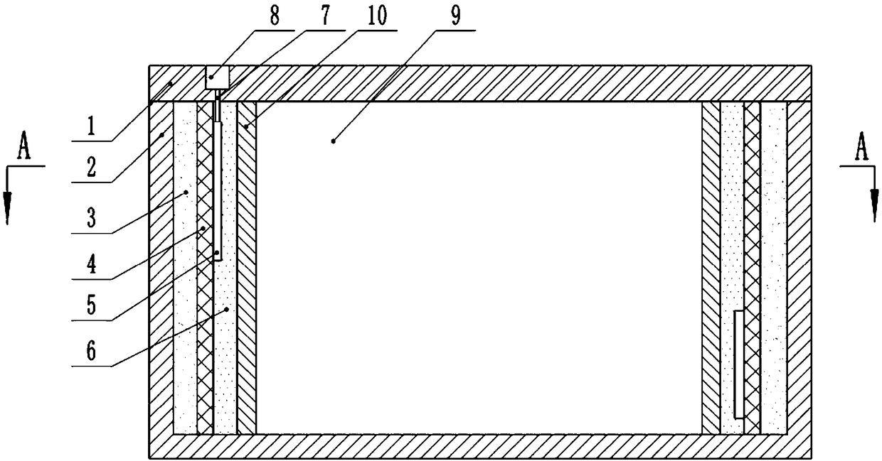
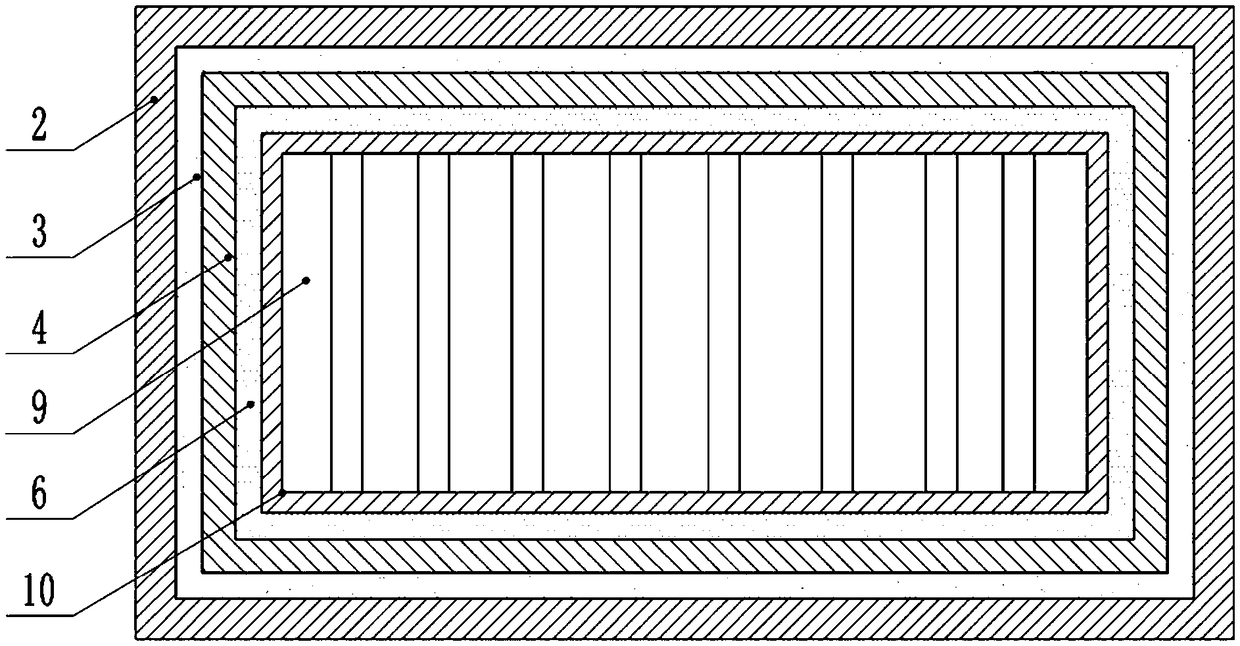
The invention belongs to the technical field of batteries, and particularly discloses a sealing method of batteries. The specific implementation process is as follows: (1) fixedly installing a pole plate group into a battery case, and leaving a space between the pole plate group and the battery case; 2) manufacturing a heat conductor, fixedly installing that heat conductor in the battery case, andpositioning the heat conductor between the electrode plate group and the battery case, wherein an electric heating wire is arranged on a side wall of the heat conductor close to the electrode plate group; 3) sealing an upper cover on the battery case; (4) energizing the electric heating wire, and filling the fluid paraffin wax between the heat conducting body and the electrode plate group, and deenergizing the electric heating wire after the paraffin wax fills the space between the heat conducting body and the electrode plate group; (5) adding A thermosetting resin between the heat conductorand the battery housing until the thermosetting resin fills the space between the heat conductor and the battery housing. This scheme uses paraffin wax and thermosetting resin to seal the battery, andthe sealing effect is good.
Description
technical field [0001] The invention belongs to the technical field of accumulators, in particular to a method for sealing an accumulator. Background technique [0002] A battery is a device that directly converts chemical energy into electrical energy. It is mainly composed of a battery case, a plate group and an electrolyte. The plate group is composed of a positive plate and a negative plate sandwiched by a diaphragm. The electrode plate group and the rectangular electric tank of the electrolyte, and the upper cover with a safety valve for sealing the opening of the electric tank. At present, most of the batteries adopt the plate pressing type battery, and several plates are pressed and fixed in the battery shell. It is inevitable to bump and vibrate during the driving process of the car. The battery with this structure is easy to be bumped and vibrated during long-term use. Part of the plate is broken, and the electrolyte is prone to leakage, which affects the input and...
Claims
Login to View More Application Information
Patent Timeline
 Patent Type & Authority Applications(China)
IPC IPC(8): H01M2/08H01M2/04H01M10/04H01M50/171H01M50/184H01M50/186H01M50/193
CPCH01M10/04H01M2220/20H01M50/166H01M50/183Y02E60/10Y02P70/50
Inventor 何幸华黎少伟李政文何可立马俊
Owner GUANGZHOU ZHUOYUE POWER NEW ENERGY CO LTD