A kind of door-heat exchanger integrated multi-layer door and equipment with multi-layer door

A door and equipment technology, applied in the field of power and communication equipment operating environment adjustment, can solve problems such as affecting the transportation of kilometers, difficult to install, and increasing the overall height of the cabin.

Active Publication Date: 2022-02-15
NANJING GUODIAN NANZI POWER GRID AUTOMATION CO LTD
View PDF0 Cites 0 Cited by
  • Summary
  • Abstract
  • Description
  • Claims
  • Application Information

AI Technical Summary

Problems solved by technology

If the equipment density in the cabin is high, the bulkhead may not have enough space to install the heat exchanger. If it is installed on the top of the cabin, it will increase the total height of the cabin and affect the kilometer transportation
Therefore, in actual engineering, there are also situations where it is difficult to install

Method used


Image

  • A kind of door-heat exchanger integrated multi-layer door and equipment with multi-layer door
  • A kind of door-heat exchanger integrated multi-layer door and equipment with multi-layer door
  • A kind of door-heat exchanger integrated multi-layer door and equipment with multi-layer door

Examples


Embodiment 1

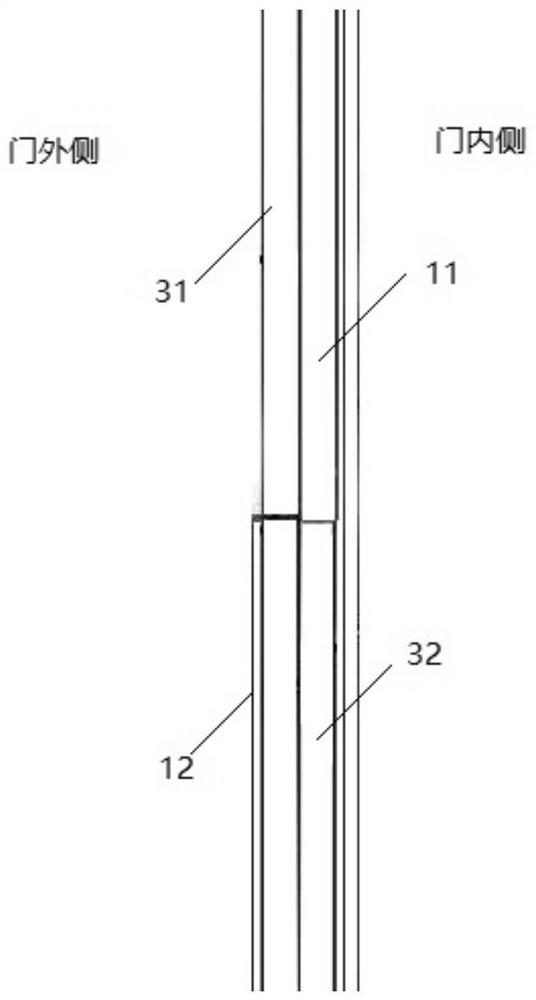
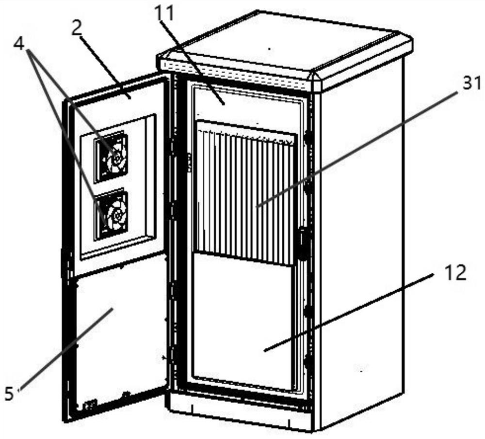
[0031] This embodiment is a kind of multi-layer door, refer to figure 1 and figure 2 As shown, the multi-layer door includes an outer door 2, an inner door 1 and a gravity heat pipe mechanism; the gravity heat pipe mechanism includes a heat releasing section 31 and a heat absorbing section 32;

[0032] The gravity heat pipe mechanism runs through and seals the middle of the inner door in the height direction, so that the heat release section 31 of the gravity heat pipe mechanism is located between the outer door and the inner door, and the heat absorption section 32 is located inside the inner door;

[0033] The outer door corresponding to the heat release section of the gravity heat pipe mechanism is provided with a heat exchange mechanism.

[0034] In this example:

[0035] Such as figure 2 As shown, the side of the outer door facing the heat release section of the gravity heat pipe mechanism is recessed to form a heat exchange chamber, and two heat exchange fans 4 are ...

Embodiment 2

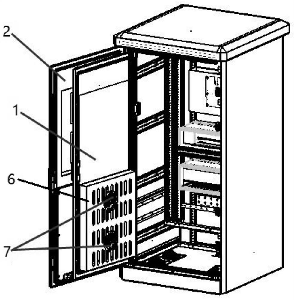
[0045] This embodiment is a cabinet or prefabricated cabin with multi-layer doors, refer to Figure 2 to Figure 6 As shown, the equipment is a cabinet, and the cabinet includes a cabinet body and a cabinet door that are rotatably connected, and the cabinet door is the multi-layer door of Embodiment 1.

[0046] Such as Figure 5 As shown, in order to further improve the heat exchange efficiency of the gravity heat pipe, a heat exchange circulation fan 9 is provided in the cabinet, which can realize the heat circulation of the entire space in the cabinet.

[0047] In this embodiment, the cabinet with double-layer doors can realize the following functions during normal operation: Figure 6 The internal and external heat cycle shown has high heat exchange efficiency.

[0048] If the equipment is a prefabricated cabin, the cabin includes a rotatably connected cabin body and a cabin door, and the cabin door is a multi-layer door. A heat exchange circulation fan is installed in th...


PUM


Abstract

The invention discloses a multi-layer door and equipment with the multi-layer door. The multi-layer door includes an outer door, an inner door and a gravity heat pipe mechanism; the gravity heat pipe mechanism includes a heat release section and a heat absorption section; And seal the middle part of the height direction of the inner door, so that the heat release section of the gravity heat pipe mechanism is located between the outer door and the inner door, and the heat absorption section is located inside the door of the inner door; A heat exchange mechanism is provided on the landing door. The multi-layer door of the present invention utilizes the gravity heat pipe technology to realize the installation and cooperation of the heat exchanger and the double-layer door, which can realize high heat exchange efficiency between the inside and outside of the cabinet or prefabricated cabin door, because the gravity heat pipe does not damage the inner door Therefore, it can achieve the sealing performance of general double-layer doors and can adapt to harsh environments, that is to say, the present invention can simultaneously achieve the purpose of double sealing and heat exchange inside and outside the cabinet or prefabricated cabin.

Description

technical field [0001] The invention relates to the technical field of electric power and communication equipment operating environment adjustment, in particular to a multi-layer door with integrated door-heat exchanger and a cabinet or cabinet with the multi-layer door, which has high sealing performance and can realize heat exchange function. Prefabricated cabins. Background technique [0002] A heat exchanger is a common thermal management device that can be used for heat exchange and transfer. In industries such as electric power and communication, a large number of equipment are provided with protection and a suitable operating environment by cabinets or prefabricated cabins. With the development of electric power construction, heat exchangers have been widely used in power cabinets or boxes that require heat dissipation. The advantages of good isolation and sealing. However, the existing heat exchange application mode basically installs the equipment on the cabinet d...

Claims


Application Information

Patent Timeline
Patent Type & Authority Patents(China)
IPC IPC(8): E06B5/00E06B5/16E06B7/23E06B7/28F28D15/02H02B1/30H02B1/56
CPCE06B5/00E06B5/16E06B7/23E06B7/28H02B1/565H02B1/30F28D15/02
Inventor 袁涤非许玉香俞春林顾锦书顾铭飞王涛杨刚史光媛
Owner NANJING GUODIAN NANZI POWER GRID AUTOMATION CO LTD
Why Eureka
Try Eureka