A method of operating a pressure control system

A technology of pressure control and operation method, applied in the direction of fluid pressure actuating device, valve absorbing fluid energy device, mechanical equipment, etc., can solve the problem that the ball cannot be accurately aligned with the valve seat mouth, the size cannot be adjusted in real time, and the function is single. problems, to achieve the effect of convenient daily maintenance

Inactive Publication Date: 2019-09-06
CHANGSHA UNIVERSITY OF SCIENCE AND TECHNOLOGY
View PDF10 Cites 0 Cited by
  • Summary
  • Abstract
  • Description
  • Claims
  • Application Information

AI Technical Summary

Problems solved by technology

[0004] 1. In the pressure control circuit of the prior art, the main drive oil circuit is the main path through which the hydraulic fluid passes, and various abnormal conditions are prone to occur. When abnormal conditions occur, such as overpressure conditions, the pipeline ruptures or other faults
[0005] 2. The gate valve is an important part of the pressure control system. The gate valve in the prior art often only has a cut-off function, and the single function cannot adapt to various complex working conditions.
[0006] 3. Due to the dynamic sealing of the check valve in the prior art, such as the cooperation of the spring, the ball and the valve seat, it is difficult to achieve good sealing
And after a long time of use, the performance of the spring decreases, and the ball cannot be accurately aligned with the valve seat.
[0007] 4. The size of the gate valve in the prior art cannot be adjusted in real time when it is specifically adapted to the working environment, especially for the driving parts. When the size of the cut-off body cannot be adjusted, the adjustment of the size of the driving parts is often particularly important
[0008] 5. The adjustment scheme of the valve stem in the prior art is often flexible enough, but not strong enough to be used for a long time under heavy load
[0009] 6. Due to the long-term use of the driving source of the prior art, more maintenance is required, and there is a lack of maintenance means in the prior art
[0010] 7. The existing technology includes a gate valve pressure control system, which often has a single function, cannot realize the energy storage function, and cannot recycle excess energy

Method used


Image

  • A method of operating a pressure control system
  • A method of operating a pressure control system
  • A method of operating a pressure control system

Examples


Embodiment Construction

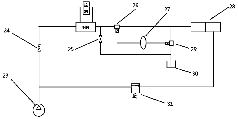
[0036] As shown in the figure: a method for operating a pressure control system, the pressure control system includes a pump, a first switch, a second switch, a first three-way valve, an accumulator, a hydraulic cylinder, a second three-way valve, and an oil tank , Solenoid valve, gate valve, control device; the operation method includes a driving method, a pressure relief method, a decompression energy storage method, and an energy storage feedback method;

[0037] As shown in the figure: the driving method is as follows: the liquid in the pump is connected to the first cavity of the hydraulic cylinder through the main circuit, and the second cavity of the hydraulic cylinder is connected through the auxiliary circuit; the main circuit includes the first cavity Switch, gate valve, first three-way valve; the auxiliary circuit includes the solenoid valve; by respectively injecting liquid into the main circuit and injecting liquid into the auxiliary circuit, the first cavity and the ...


PUM


Abstract

The invention discloses an operation method of a pressure control system. The pressure control system comprises a pump, a first switch, a second switch, a first three-way valve, an energy accumulator,an hydraulic cylinder, a second three-way valve, an oil tank, a solenoid valve, a gate valve, and a control device; the operation method comprises a driving method, a pressure relief method, a pressure reduction and energy storage method, and an energy storage feedback method, the energy storage feedback method comprises the following parts: the downstream end of the energy accumulator is connected to the second three-way valve; the three ends of the second three-way valve are respectively connected with the main circuit, the energy accumulator and the oil tank; the main circuit comprises a branch circuit of the energy accumulator, and the branch circuit parallel of the second switch; a second pressure sensor is arranged in the energy accumulator; a pressure signal of the second pressuresensor is fed back to the control device; when the control device judges that the energy accumulator needs to release the energy for feedback, the control device controls the energy accumulator to start, and controls the second three-way valve to connect with the energy accumulator and the first cavity.

Description

Technical field [0001] The invention relates to the field of fluid control, and in particular to an operating method of a pressure control system. Background technique [0002] In the pressure control system, the hydraulic cylinder execution system is a commonly used execution system, which controls the reciprocating movement and drive of the hydraulic cylinder through the hydraulic drive main circuit and the hydraulic drive branch circuit. Gate valve is a common component among them. [0003] In actual use, the existing pressure control system and its gate valve have the following problems: [0004] 1. In the pressure control circuit of the prior art, the main driving oil circuit is the main path through which the hydraulic fluid passes, and various abnormal working conditions are often prone to occur. When an abnormality occurs, for example, an overpressure condition may occur, causing the pipeline to rupture Or other failures. [0005] 2. The gate valve is an important part of th...

Claims


Application Information

Patent Timeline
Patent Type & Authority Patents(China)
IPC IPC(8): F15B13/04F15B1/02F16K3/02F16K3/314F16K3/30F16K3/36F16K47/04
Inventor 李方义严宇飞高嘉飞王鑫
Owner CHANGSHA UNIVERSITY OF SCIENCE AND TECHNOLOGY
Why Eureka
Try Eureka