Telescopic mechanism for hand-held weeding machine
A telescopic mechanism and a weeding machine technology, applied in the field of weeding machines, can solve the problem that the length of the hand-held part of the hand-held weeding machine is not adjustable, and achieve the effects of convenient expansion, labor saving, and labor intensity reduction.
- Summary
- Abstract
- Description
- Claims
- Application Information
AI Technical Summary
Problems solved by technology
Method used
Image

Examples
Embodiment 1
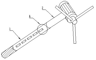
[0028] combined with Figure 1-6 As shown, a telescopic mechanism of a hand-held weeder includes a hand-held rod 1 and a moving rod 2 on which the weeder is installed. The motor of the switch, the rotating shaft of the motor is connected with a screw 3, the screw 3 is connected with the moving rod 2 and the axis line of the screw 3 is parallel to the long axis of the moving rod 2.
[0029] The present invention is a new telescoping mechanism of a hand-held weeder. A moving rod 2 is set inside a hand-held rod 1 to control the relative movement of the moving rod 2 and the hand-held rod 1 to realize telescoping. A motor is installed in the hand-held rod 1 and connected to Power supply and switch, through the switch to control the forward and reverse rotation of the motor, the screw rod 3 connected to the motor is driven to rotate, and the screw rod 3 is connected to the moving rod 2, and the rotation of the screw rod 3 makes the position of the moving rod 2 and the hand-held rod ...
Embodiment 2
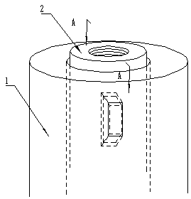
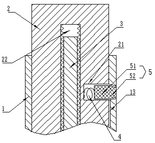
[0031] This embodiment is based on the above embodiments, combined with the attached Figure 2-4 As shown, further defined, the side wall of the moving rod 2 is provided with a mounting groove 21, the bottom of the mounting groove 21 is installed with a spring 4, and the end of the spring 4 away from the bottom of the mounting groove 21 is connected to the A key 5 , the side wall of the handle bar 1 is provided with an A groove 11 matching with the A key 5 . Wherein the connection of installation groove 21, spring 4 and A key 5 makes the movement of moving rod 2 partially limited, thereby can move according to the direction required, and A key 5 can compress spring 4 and enter the inside of installation groove 21 to generate in moving rod 2 It is not affected by exercise.
[0032] Other parts of this embodiment are the same as those of the foregoing embodiments, so details are not repeated here.
Embodiment 3
[0034] This embodiment is based on the above embodiments, combined with the attached figure 2 As shown, it is further defined that the A key 5 includes an A part 52 and a B part 51 connected to the spring 4, and the surfaces of the A part 52 close to the motor and away from the motor are both wedge-shaped surfaces and the two wedge-shaped surfaces are "eight" The "eight"-shaped bottoms of the two wedge-shaped surfaces are connected to the B part 51, and the B part 51 is installed in the installation groove 21. Wherein, the wedge-shaped surface of "eight" shape is set, so that the moving rod 2 can be stretched or retracted without locking when moving in the required direction.
[0035] Other parts of this embodiment are the same as those of the foregoing embodiments, so details are not repeated here.
PUM
 Abstract
Description
Claims
Application Information
 - R&D
- Intellectual Property
- Life Sciences
- Materials
- Tech Scout
- Unparalleled Data Quality
- Higher Quality Content
- 60% Fewer Hallucinations
Browse by: Latest US Patents, China's latest patents, Technical Efficacy Thesaurus, Application Domain, Technology Topic, Popular Technical Reports.
© 2025 PatSnap. All rights reserved.Legal|Privacy policy|Modern Slavery Act Transparency Statement|Sitemap|About US| Contact US: help@patsnap.com