Two-face machining method for blank

A double-sided processing and blank technology, which is applied in the field of double-sided processing of blanks, can solve problems such as workpiece modeling defects, achieve the effects of reducing positioning deviation, accurate positioning, and improving modeling defects

Active Publication Date: 2019-01-25
青岛宙庆工业设计有限公司
View PDF10 Cites 2 Cited by
  • Summary
  • Abstract
  • Description
  • Claims
  • Application Information

AI Technical Summary

Problems solved by technology

[0005] The main purpose of the present invention is to provide a double-sided processing method for a blank, so as to solve the problem in the prior art that the workpiece has obvious shape defects caused by the positioning deviation between the two surfaces of the blank

Method used


Image

  • Two-face machining method for blank
  • Two-face machining method for blank
  • Two-face machining method for blank

Examples


Embodiment 1

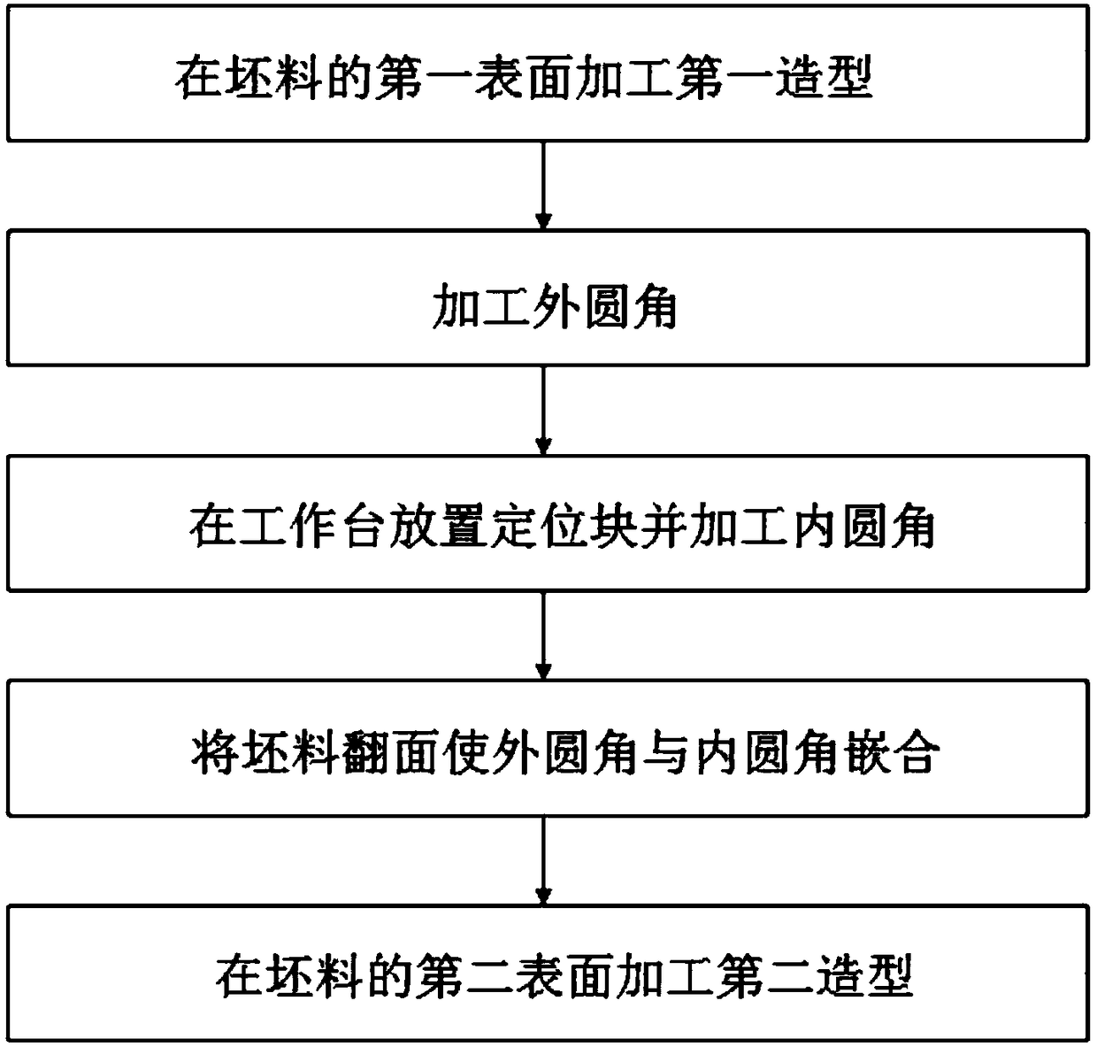
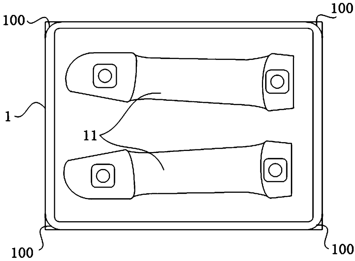
[0059] Such as Figure 2a As shown, in this embodiment, the blank 1 is first placed on the workbench, with the first surface of the blank 1 facing up and the second surface facing down, and the first surface of the blank 1 is processed by cutting the shape of one side of the workpiece - the first molding 11, and then cutting the four outer corners of the first surface of the blank 1 to form a bullnose 100, the radiuses of the four bullnose are the same.

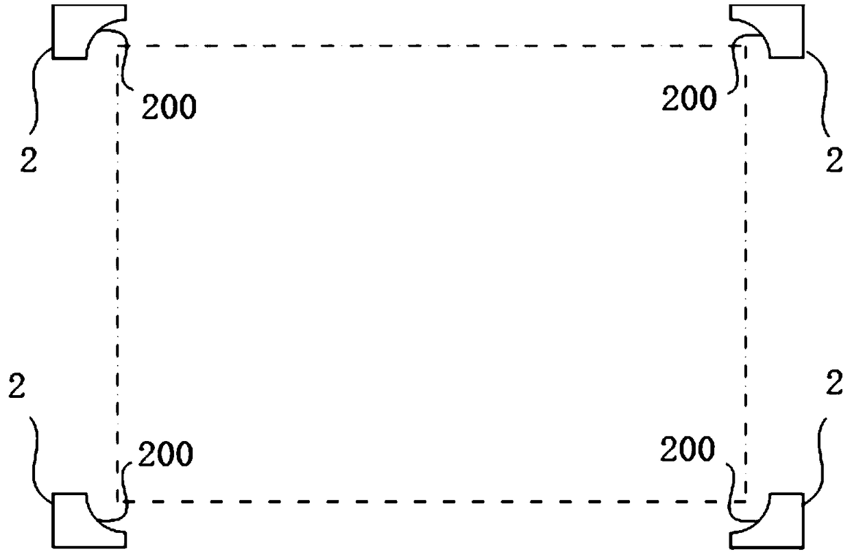
[0060] Such as Figure 2b As shown, after removing the blank from the workbench, place four corresponding positioning blocks 2 on the workbench with reference to the mirror image position of the outer fillet, and then cut and process the mirror image of the corresponding outer fillet on each positioning block 2 Fillet 200. Since the radii of the four outer fillets in this embodiment are the same, there is no need to specifically select whether the mirroring mode is up-down mirroring or left-right mirroring.

[0061] Such a...

Embodiment 2

[0065] The difference between this embodiment and Embodiment 1 lies in that the diameters of the four outer fillets of the first surface are different. In this case, the mirroring direction needs to be determined in advance. The mirroring direction in this embodiment is up-and-down mirroring.

[0066] Such as Figure 3a As shown, in this embodiment, the blank 1 is first placed on the workbench, with the first surface of the blank 1 facing up and the second surface facing down, and the first surface of the blank 1 is processed by cutting the shape of one side of the workpiece 11. Then cut the two outer corners on the left side of the first surface of the blank 1 to form two outer corners with the same radius size, and cut the two outer corners on the right side to form two outer corners with the same radius size. For purposes of distinction, the bullnose on the left is marked as left bullnose 100a, the bullnose on the right is marked as right bullnose 100b, and the radius of ...

Embodiment 3

[0072] This embodiment is a simplified form, and the difference from the above embodiment is that only the two outer corners on the left side of the first surface of the blank 1 are cut into bull fillets, and correspondingly, only the corresponding positioning block. Such a setting can also realize the positioning after turning over and avoid the wrong direction of turning over.

[0073] See the specific process Figure 4a-Figure 4d , first place the blank 1 on the workbench, make the first surface of the blank 1 face up and the second surface face down, and process the first shape 11 of the workpiece on the first surface of the blank 1 by cutting, and then place the blank 1 The two outer corners on the left side of the first surface of the first surface are cut to form two outer corners with the same radius size 100; then after the blank is removed from the table, place the corresponding two outer corners on the left side of the table with reference to the mirror image posit...


PUM


Abstract

The invention relates to the technical field of machining, in particular to a two-face machining method for a blank. In the method, outer circle corners are machined in the first surface of the blank,so that positioning structures are reserved after the blank is turned; inner circle corners corresponding to the outer circle corners are machined on positioning blocks, so that the effect of position finding in secondary cutting after the blank is turned; the radius of the inner circle corners formed by cutting of the positioning blocks is equal to that of the corresponding outer circle corners,the outer circle corners and the inner circle corners can be completely embedded to realize accurate positioning after the blank is turned, in this way, the positioning deviation between the two faces of the blank can be reduced, and modeling defects, existing in workpieces, caused by the positioning deviation are overcome.

Description

technical field [0001] The invention relates to the technical field of mechanical processing, in particular to a double-sided processing method for a blank. Background technique [0002] The car model can be used in trial production, verification and other stages before the product goes offline. Common car models include yogi models, clay models, etc. Among them, the yogi model is also called a hard model, and the blank used in the yogi model needs to be formed by machining. [0003] For model workpieces with complex modeling surfaces, it is usually not open mold casting like traditional quantitative workpieces, but needs to be cut separately from the two sides of the blank. [0004] Double-sided cutting involves repositioning of the blank after it has been turned over. However, there is no effective repositioning method in the prior art. As a result, the positioning between the two sides of the blank is prone to deviation, resulting in obvious shape defects in the workpie...

Claims


Application Information

Patent Timeline
Patent Type & Authority Applications(China)
IPC IPC(8): B27M1/08B28B15/00B28B17/00
CPCB27M1/08B28B15/00B28B17/00
Inventor 吴燕民邱教练
Owner 青岛宙庆工业设计有限公司
Why Eureka
Try Eureka