Temperature control system of an electric vehicle

A technology for temperature control systems and electric vehicles, applied to vehicle parts, heating/cooling equipment, air handling equipment, etc., can solve the problems of inability to heat batteries, low heat dissipation efficiency, and affecting use, and achieve a reasonable structure and strong practicability Effect

Inactive Publication Date: 2019-01-25
TAIZHOU DECHENG ELECTRIC APPLIANCES
View PDF0 Cites 10 Cited by
  • Summary
  • Abstract
  • Description
  • Claims
  • Application Information

AI Technical Summary

Problems solved by technology

[0002] With the development of society, cars have gradually become a necessary means of transportation for every family. At present, the vast majority of cars use gasoline as fuel for driving, and some cars have been changed to gas as power, but whether it is gasoline or gas, In the process of use, a large amount of waste gas will be generated, and the direct discharge of waste gas into the air will increase the speed of environmental pollution, making our living environment worse
In order to protect the environment, a new type of car that uses electricity as energy has been gradually introduced to the market. The car is equipped with a large-capacity battery, and the engine is driven by electricity to run. Although the electric car is energy-saving and environmentally friendly, the battery is in the process of charging and discharging. It will emit a lot of heat, and when the temperature of the battery is lower than 0°C or higher than 50°C, it is prone to failure, which will shorten the life of the battery, so the temperature control of the battery is particularly important
At present, the heat dissipation of batteries in electric vehicles is mostly carried out by radiators. The heat dissipation efficiency is low, and the batteries cannot be heated. As a result, electric vehicles are not suitable for charging and discharging in cold winter, which affects normal use.

Method used


Image

  • Temperature control system of an electric vehicle
  • Temperature control system of an electric vehicle
  • Temperature control system of an electric vehicle

Examples


Embodiment Construction

[0027] The present invention will be further described below in conjunction with accompanying drawing:

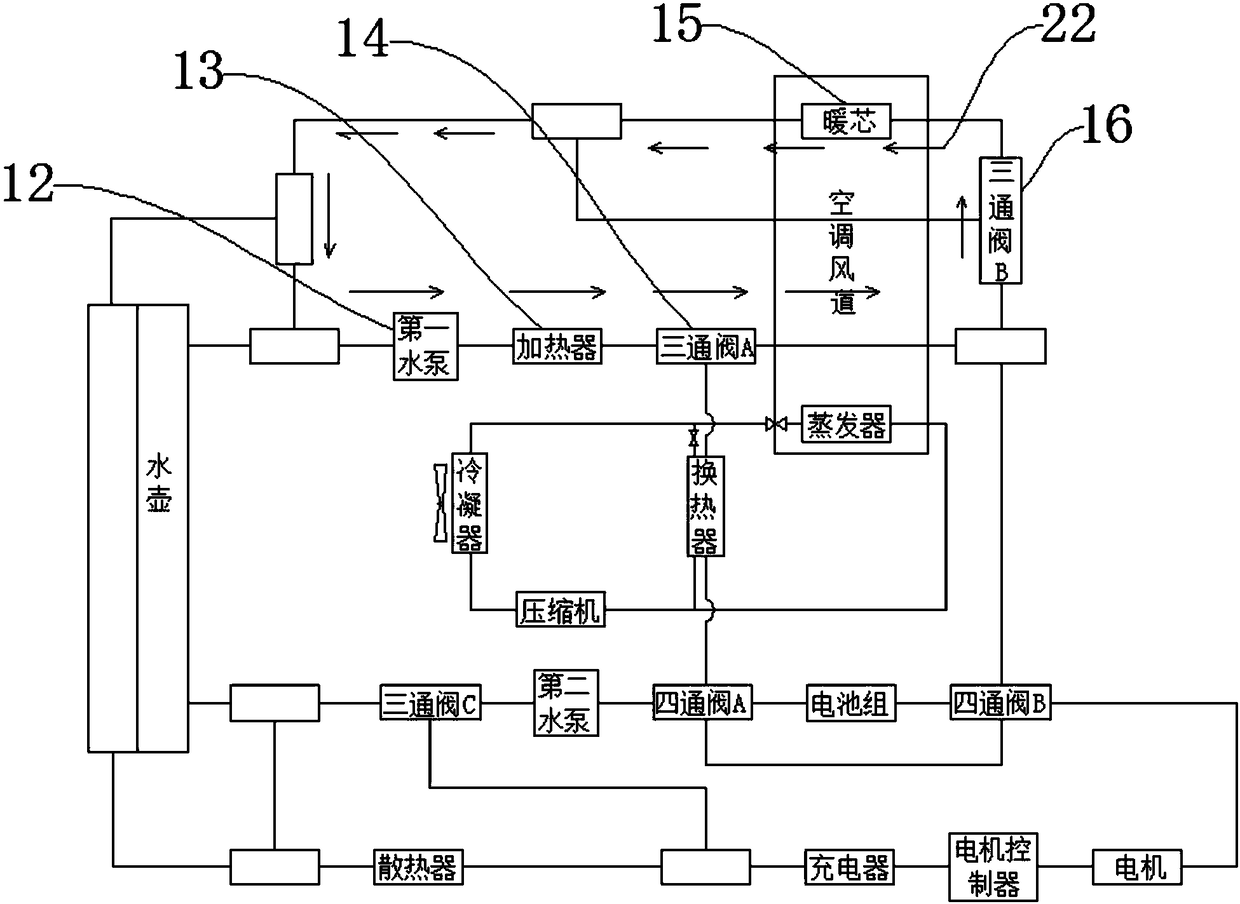
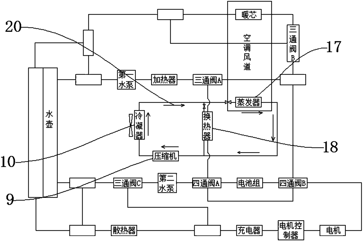
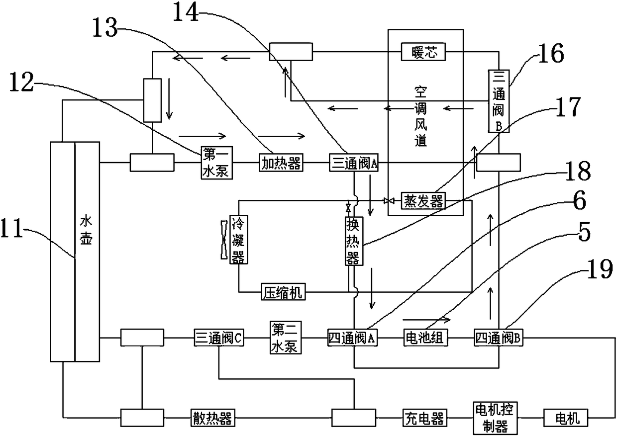
[0028] Such as Figure 1-Figure 10 As shown, a vehicle temperature control system for an electric vehicle includes the kettle 11 and the motor controller 3. One end of the kettle 11 is connected to the first water pump 12, and the first water pump 12 is connected to the A heater 13, the heater 13 is connected to the three-way valve A14, one end of the three-way valve A14 is connected to the three-way valve B16, and the other end of the three-way valve A14 is connected to the heat exchanger 18 , the three-way valve B16 is connected with the warm core 15, the heat exchanger 18 is connected with the compressor 9, the compressor 9 is connected with the condenser 10, and the condenser 10 is connected with The evaporator 17, the heat exchanger 18 is connected with the four-way valve A6, the battery pack 5 is arranged on one side of the four-way valve A6, and the four-way valve B...


PUM


Abstract

The invention discloses a temperature control system for an electric vehicle including a kettle and a controller; at one end of that kettle, a first water pump is connected, the first pump is connected with a heater, the heater is connected with a three-way valve A, at one end of that three-way valve A is connected with a three-way valve B, at the other end of the three-way valve A is connected with a heat exchanger, the three-way valve B is connected with a heating core, the heat exchanger is connected with a compressor, the compressor is connected with a condenser, the condenser is connectedwith an evaporator, the heat exchanger is connected with a four-way valve A, a battery pack is arranged on one side of the four-way valve A, a four-way valve B is arranged beside the battery pack, the four-way valve B is connected with a motor, the motor is connected with a motor controller, and the motor controller is connected with a charger. The invention has the advantages of having a plurality of working modes, thereby realizing the temperature regulation of the battery system and the transmission system, and ensuring the normal use of the automobile in different environments, and has reasonable structure and strong practicability.

Description

technical field [0001] The invention relates to the technical field of automobile thermal management, in particular to a temperature control system for a complete electric automobile. Background technique [0002] With the development of society, cars have gradually become a necessary means of transportation for every family. At present, the vast majority of cars use gasoline as fuel for driving, and some cars have been changed to gas as power, but whether it is gasoline or gas, In the process of use, a large amount of exhaust gas will be generated, and the direct discharge of exhaust gas into the air will increase the speed of environmental pollution, making our living environment worse. In order to protect the environment, a new type of car that uses electricity as energy has been gradually introduced to the market. The car is equipped with a large-capacity battery, and the engine is driven by electricity to run. Although the electric car is energy-saving and environmental...

Claims


Application Information

Patent Timeline
Patent Type & Authority Applications(China)
IPC IPC(8): B60H1/00
CPCB60H1/00271B60H1/00278B60H1/00392B60H1/00899B60H2001/00307B60H2001/00935
Inventor 杨玲敏
Owner TAIZHOU DECHENG ELECTRIC APPLIANCES
Why Eureka
Try Eureka