A multi-rotor vertical take-off and landing aircraft

A vertical take-off and landing aircraft and multi-rotor technology, applied in vertical take-off and landing aircraft, rotorcraft, aircraft control, etc., can solve the problems of inability to hover in the air, low energy efficiency, short flight range, etc., and improve the stability of lateral navigation , improve stability, and ensure the effect of stability

Inactive Publication Date: 2019-01-25
FOSHAN SHENFENG AVIATION SCI & TECH
View PDF0 Cites 0 Cited by
  • Summary
  • Abstract
  • Description
  • Claims
  • Application Information

AI Technical Summary

Problems solved by technology

[0002] As we all know, fixed-wing aircraft use the relative airflow movement of the wings to generate lift to resist gravity, and use the deflection of the rudder surface to control. It has the advantages of fast flight speed, long range, heavy load, and high energy efficiency. Realize hovering in the air; the rotorcraft uses one or more rotors to generate pulling force against gravity, and provides the power of the horizontal movement of the aircraft by controlling the rotation plane of the rotors and the inclination angle of the horizontal plane. It has a simple structure, can take off and land vertically and hover in the air. The advantages and disadvantages are slow speed, short range, small load, and low energy efficiency; therefore, many people have always wanted to combine the high flight efficiency of fixed-wing aircraft with the advantages of hovering and vertical take-off and landing of rotary-wing aircraft.

Method used


Image

  • A multi-rotor vertical take-off and landing aircraft
  • A multi-rotor vertical take-off and landing aircraft
  • A multi-rotor vertical take-off and landing aircraft

Examples


Embodiment Construction

[0026] The following will clearly and completely describe the technical solutions in the embodiments of the present invention with reference to the accompanying drawings in the embodiments of the present invention. Obviously, the described embodiments are only some, not all, embodiments of the present invention. Based on the embodiments of the present invention, all other embodiments obtained by persons of ordinary skill in the art without making creative efforts belong to the protection scope of the present invention.

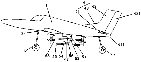
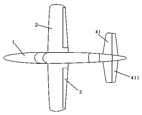
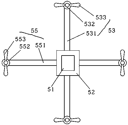
[0027] Please refer to the attached Figure 1-3 , the present invention provides a multi-rotor vertical take-off and landing aircraft, comprising: a fuselage 1, a main wing 2, an auxiliary wing 3, an empennage 4 and a multi-rotor assembly, wherein the main wing 2 is symmetrically arranged on both sides of the fuselage 1 , the auxiliary wing 3 is connected to the tail end of the main wing 2, the empennage 4 is arranged at the tail end of the fuselage 1, and the...


PUM


Abstract

The invention discloses a multi-rotor vertical take-off and landing aircraft, comprising a fuselage, a main wing, an aileron, a tail wing and a multi-rotor assembly. The main wing is symmetrically arranged on both sides of the fuselage, the aileron is connected with the tail end of the main wing, the tail wing is arranged at the tail end of the fuselage, and the multi-rotor assembly is arranged atthe bottom end of the fuselage. The multi-rotor assembly comprises a first motor, a connecting plate, a first rotor, a second motor and a second rotor. The first motor is fixedly mounted on the bottom end of the fuselage and is connected with the connecting plate through a rotating shaft. The first rotor is symmetrically mounted on both sides of the connecting plate, and the second motor is mounted on the bottom end of the connecting plate and is connected with the second rotor through the rotating shaft. The invention not only realizes the vertical take-off and landing and the air hovering of the aircraft, but also improves the flight stability of the aircraft.

Description

technical field [0001] The invention relates to the technical field of unmanned aerial vehicle equipment, and more specifically relates to a multi-rotor vertical take-off and landing aircraft. Background technique [0002] As we all know, fixed-wing aircraft use the relative airflow movement of the wings to generate lift to resist gravity, and use the deflection of the rudder surface to control. It has the advantages of fast flight speed, long range, heavy load, and high energy efficiency. Realize hovering in the air; the rotorcraft uses one or more rotors to generate pulling force against gravity, and provides the power of the horizontal movement of the aircraft by controlling the rotation plane of the rotors and the inclination angle of the horizontal plane. It has a simple structure, can take off and land vertically and hover in the air. The advantages and disadvantages are slow speed, short range, small load, and low energy efficiency; therefore, many people have always ...

Claims


Application Information

Patent Timeline
Patent Type & Authority Applications(China)
IPC IPC(8): B64C27/22B64C29/00B64C9/00B64C5/02B64C5/06
CPCB64C27/22B64C5/02B64C5/06B64C9/00B64C29/0008
Inventor 李玉龙王志成
Owner FOSHAN SHENFENG AVIATION SCI & TECH
Why Eureka
Try Eureka