a dispensing column

A technology of pipe injection and pipe string, applied in the field of oil and gas field exploitation, can solve the problems of high construction cost, inability to trip the pipe string without killing the well, and achieve the advantages of reducing the construction cost, avoiding the killing operation, and avoiding the loss of formation water injection energy. Effect

Active Publication Date: 2022-03-22
CHINA PETROLEUM & CHEM CORP +1
View PDF17 Cites 0 Cited by
  • Summary
  • Abstract
  • Description
  • Claims
  • Application Information

AI Technical Summary

Problems solved by technology

[0004] The purpose of the present invention is to provide a separate injection pipe string to solve the technical problems in the prior art that the pipe string cannot be tripped without snubbing and the construction cost is high

Method used


Image

  • a dispensing column
  • a dispensing column
  • a dispensing column

Examples


Embodiment Construction

[0033] Embodiments of the present invention will be further described below in conjunction with the accompanying drawings.

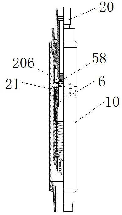
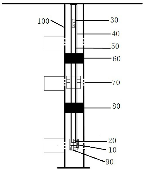
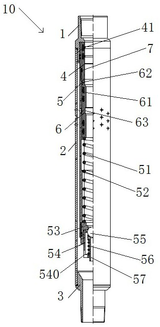
[0034] A specific embodiment of the dispensing column of the present invention, such as Figure 1 to Figure 8 As shown, a distributing pipe string includes an outer pipe and an inner pipe located inside the outer pipe, and an annular cavity for injecting water into the upper formation is formed between the inner pipe and the outer pipe, wherein the outer pipe includes sequentially arranged from top to bottom The large pipe string 40, the first packer 60, the one-way valve 70, the second packer 80, the downhole switch 10 and the plug 90, the inner pipe includes the preset mandrel 30 arranged in sequence from top to bottom, the small pipe The column 50 and the intubation tube 20, the bottom water injection channel and the movable spool 6 are provided on the downhole switch 10, and the driving part 203 is provided on the intubation tube 20, and the driving ...


PUM


Abstract

The invention relates to a dispensing column. The dispensing string includes an outer pipe and an inner pipe located inside the outer pipe. An annular cavity for injecting water into the upper formation is formed between the inner pipe and the outer pipe. The outer pipe is provided with a bottom water injection channel. There is a sealing structure that separates the bottom water injection channel from the ring cavity. The outer pipe is equipped with a movable valve core for controlling the opening and closing of the bottom water injection channel at the bottom water injection channel. The movable spool is driven to control the driving member for opening the bottom water injection channel, and the inner tube has an internal water injection channel for communicating the inner cavity of the inner tube with the bottom water injection channel when the bottom water injection channel is opened. The distributing pipe string controls the on-off of the water injection channel at the bottom of the outer pipe through the driving part provided under the inner pipe, which avoids the use of killing fluid for well killing operations and greatly reduces the construction cost.

Description

technical field [0001] The invention relates to the field of oil and gas field exploitation, in particular to a split injection pipe string. Background technique [0002] As the oilfield enters the later stage of development, the water injection pressure continues to increase. In order to ensure safe production, it is necessary to release the pressure or kill the well before operating the pipe string. The use of pressure relief means increases the construction period, wastes injection energy, and easily damages the casing due to the large change in pressure difference. On the one hand, the use of high-density well killing fluid increases the operation and construction costs. On the other hand, well killing is easy to cause pollution to the formation, and the formation is crushed to death, resulting in a sharp drop in the permeability of the reservoir near the wellbore, and the oil, gas and water in the formation cannot flow into the wellbore. . [0003] The utility model p...

Claims


Application Information

Patent Timeline
Patent Type & Authority Patents(China)
IPC IPC(8): E21B43/20E21B17/00
CPCE21B17/00E21B43/20
Inventor 马宏伟丁连民杨佰阳刘科伟沈威王新志焦明远陈平
Owner CHINA PETROLEUM & CHEM CORP
Why Eureka
Try Eureka