
Device and method for heating butterfly valve

A technology of heating device and butterfly valve, which is applied in the direction of valve heating/cooling device, valve device, lifting valve, etc., which can solve the problems such as inability to open, achieve the effect of compact structure, easy operation, improved work efficiency and safety performance

Inactive Publication Date: 2019-01-25
DALIAN INST OF CHEM PHYSICS CHINESE ACAD OF SCI
View PDF5 Cites 4 Cited by
  • Summary
  • Abstract
  • Description
  • Claims
  • Application Information

AI Technical Summary

Problems solved by technology

[0005] The invention provides a butterfly valve heating device and method, which solves the problem that the butterfly valve installed in the pipeline containing condensable gas cannot be opened due to the adhesion of the butterfly plate and the valve body due to gas condensation, so that the faulty The butterfly valve is easy to open to ensure the normal operation of the system

Method used


Image

  • Device and method for heating butterfly valve
  • Device and method for heating butterfly valve
  • Device and method for heating butterfly valve

Examples


Embodiment 1

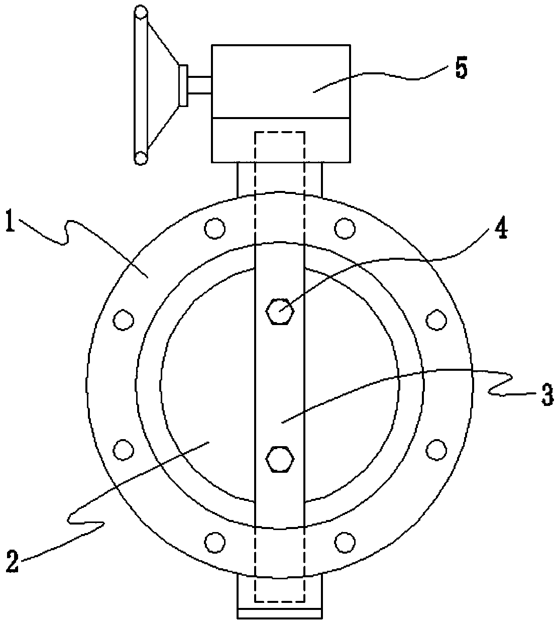
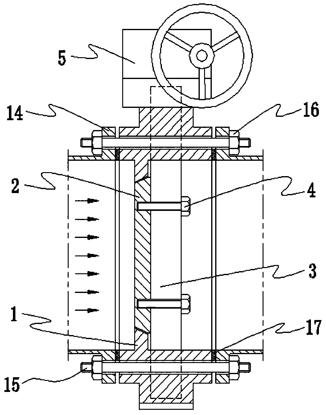
[0026] Such as figure 1 with figure 2 As shown, the general-purpose butterfly valve used in the gas pipeline is mainly composed of a valve body 1, a butterfly plate 2, a main shaft 3, a main shaft connecting bolt 4 and an actuator 5. The actuator 5 can be manual, electric or pneumatic, and the butterfly valve body 1 is placed Place the pipeline gasket 17 between the two pipeline flanges 14 and between the pipeline flange 14 and the valve body 1, the pipeline connecting bolts 15 pass through the bolt holes of the pipeline flange 14 and the valve body 1, and both ends are inserted into the pipeline Attach the nut 16 and tighten so that the fluid in the pipe will not flow out. In order to meet the requirements of processing the sealing surface, the valve body 1 is designed as a structure that partially shrinks inward, forming an inward boss, and the annular inner surface of the boss is processed as the sealing surface corresponding to the butterfly plate 2. The flow direction ...


PUM


Abstract

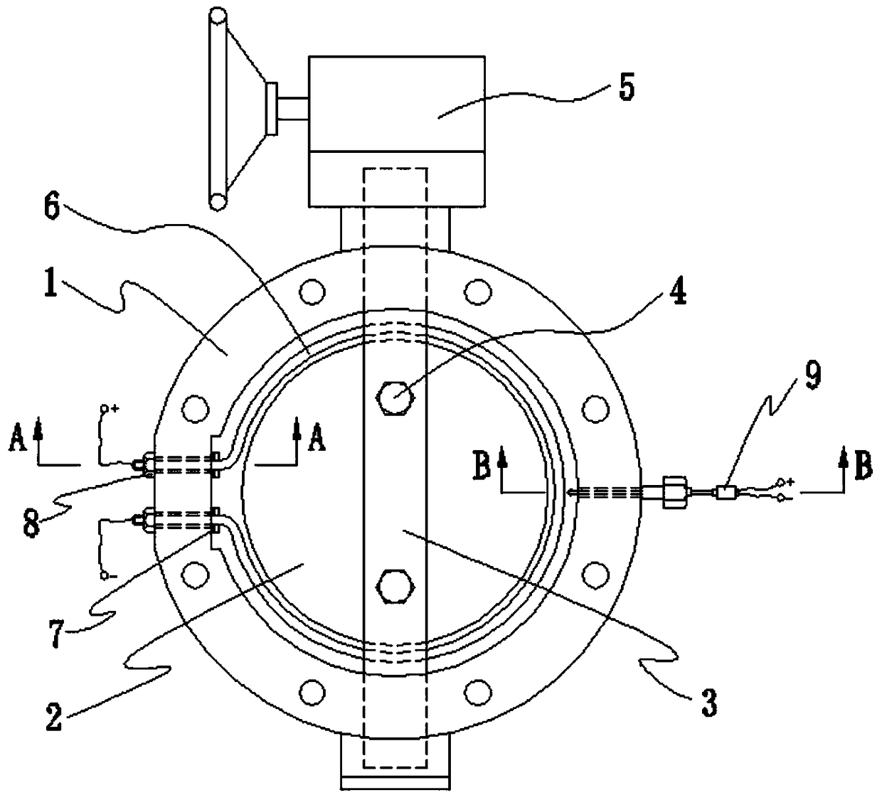
The invention discloses a device and method for heating a butterfly valve, and belongs to the technical field of mechanical engineering. According to the device for heating the butterfly valve, an omega-shaped groove is processed on the side surface of a lug boss in a valve body close to the sealing surface of the butterfly plate and the valve body. A heating pipe is arranged in the groove, and two heating pipe holes are formed in the middle part of the side surface of the valve body and on the same plane with the groove. Guide lines are respectively led out from the heating pipe and straightsections at two ends of the heating pipe, and the guide lines are connected with an external power supply. The heating pipe is attached to the valve body by the heating pipe fixing the nut and sealedby a heating pipe gasket. A counter bored hole is arranged on the side surface of an inner lug boss in the middle part of the other side of the valve body, and the valve body is provided with an outward hole which penetrates through the valve body. The outer surface of the valve body is welded with a thermocouple connecting base, and the thermocouple penetrates through a thermocouple joint and thevalve body from outside to inside and is inserted into the counter bored hole to be jointed with the valve body for measuring the temperature of the valve body. When the heating pipe is electrified and heated, the temperature of the valve body reaches the required temperature and the butterfly valve can be opened, the power supply can be cut off. The device for heating the butterfly valve has theadvantages of compact structure and easy operation, thereby troubleshooting online, guaranteeing the operation of system, and improving the working efficiency and the safety performance.

Description

technical field [0001] The invention belongs to the technical field of mechanical engineering, and relates to a device and method for heating a butterfly valve. Background technique [0002] At present, in many chemical systems, butterfly valves are often used as fluid control components due to their advantages such as short structural length, light weight, and high cost performance, and are relatively common valves. In pipelines for gas transportation, including vacuum pipelines, butterfly valves are the most commonly used valves. [0003] In a certain chemical reaction system, the product of the reaction is a mixture of various gases, including iodine, which is a condensable gas at room temperature. This iodine vapor is a gas at high temperature, becomes liquid and solid as the temperature drops, and becomes a hard solid at normal temperature. The gas circulation pipeline is equipped with a butterfly valve to control the flow. After long-term operation, iodine vapor will...

Claims


Application Information

Patent Timeline
IPC IPC(8): F16K1/22F16K1/32F16K1/36F16K27/02F16K49/00
CPCF16K1/22F16K1/32F16K1/36F16K27/0218F16K49/002
Inventor 李永钊耿自才王晓军房本杰李庆伟
Owner DALIAN INST OF CHEM PHYSICS CHINESE ACAD OF SCI
Learn More