Heat dissipation assembly and electrical oil heater

A technology of heat dissipation components and heat sinks, which is applied in electric heating systems, household heating, heating methods, etc., can solve the problems of increasing oil volume, increasing raw materials, increasing production costs, etc., to reduce surface temperature and improve heat dissipation. Efficiency, the effect of improving thermal efficiency

Pending Publication Date: 2019-01-25
NINGBO SINGFUN ELECTRIC APPLIANCE
View PDF0 Cites 0 Cited by
  • Summary
  • Abstract
  • Description
  • Claims
  • Application Information

AI Technical Summary

Problems solved by technology

[0002] In the related technology, the heat dissipation area of ​​the heat dissipation sheet of the electric heating oil heater is small, so that the heat dissipation speed of the heat dissipation sheet is relatively slow, resulting in low heat dissipation efficiency of the electric heating oil heater
The existing solution is to extend the length of the heat sink, but this increases the raw materials used, increases the production cost, and increases the volume of the oil

Method used


Image

  • Heat dissipation assembly and electrical oil heater
  • Heat dissipation assembly and electrical oil heater
  • Heat dissipation assembly and electrical oil heater

Examples


Embodiment 1

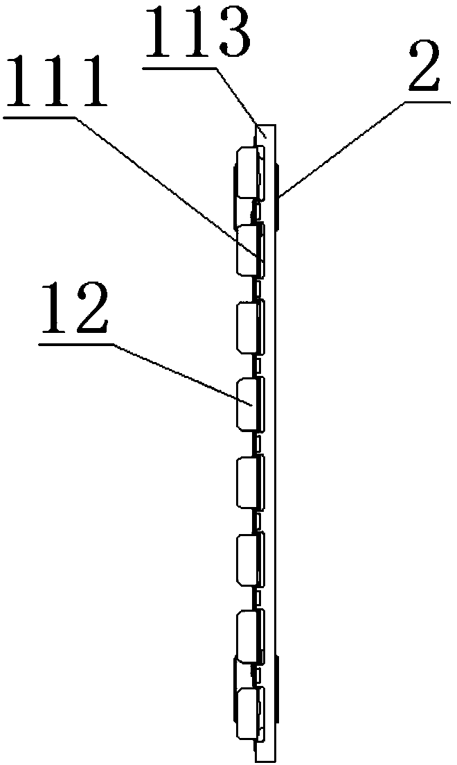
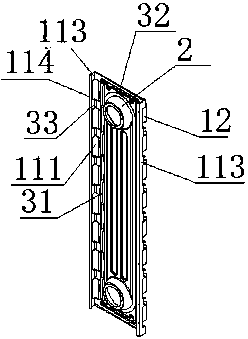
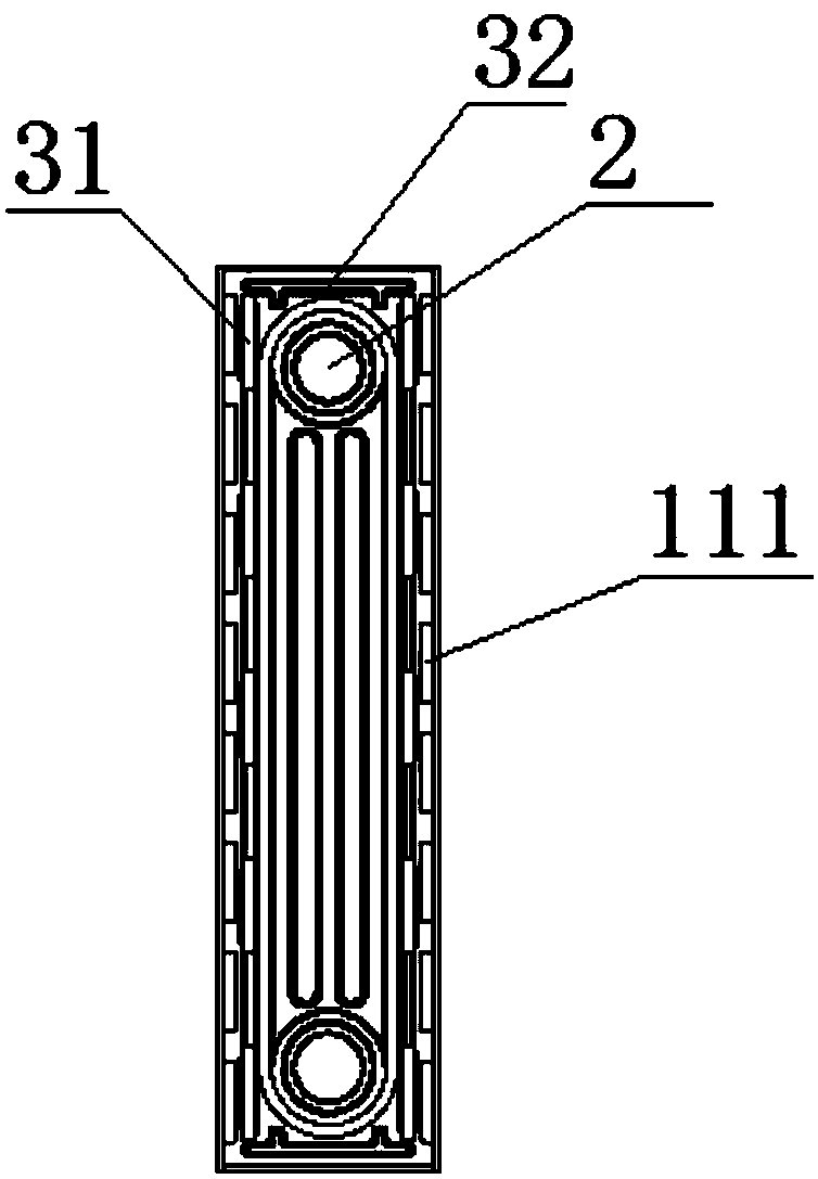
[0057] Such as Figure 24 As shown, the heat sink sub-fins 12 and the heat sink body 11 on the same heat dissipation sheet are respectively bent to the same side of the plane 21 where the heating body is located. The fin body 11 includes a connection portion 112 and a first heat dissipation edge 113, one side of the connection portion 112 is connected to one side of the heating body 2, and the other side is connected to the first heat dissipation edge 113, and the first heat dissipation edge 113 is connected to the other side of the connection portion 112. A heat dissipation edge 113 protrudes to one side relative to the plane 21 where the heating body is located; one side of the heat dissipation sub-fin 12 is connected to the connecting portion 112 .

[0058] In this way, the first airflow channel 10b and the first airflow channel 11b are formed at intervals, wherein the first airflow channel 10b forms an annular airflow channel, which maximizes the chimney effect, thereby in...

Embodiment 2

[0061] Such as Figure 25 As shown, the heat dissipation sub-fins 12 and the heat dissipation fin body 11 on the same heat dissipation sheet are respectively bent to both sides of the plane 21 where the heating body is located.

[0062] The plurality of heat dissipation sheets also include a third heat dissipation sheet 12a, and the first heat dissipation sheet 10a, the second heat dissipation sheet 11a and the third heat dissipation sheet 12a are sequentially connected;

[0063] The heat dissipation sub-sheet 12 of the second heat dissipation sheet 11a is bent toward the direction of the third heat dissipation sheet 12a, and the heat dissipation sub-sheet 12 of the third heat dissipation sheet 12a is bent toward the direction of the second heat dissipation sheet 11a In other words, an annular first airflow channel 11b is formed between the heat dissipation fins 1 of the second heat dissipation sheet 11a and the heat dissipation fins 1 of the third heat dissipation sheet 12a. ...


PUM


Abstract

The invention relates to a heat dissipation assembly and an electrical oil heater. The heat dissipation assembly comprises multiple single heat dissipation fins connected in sequence, each single heatdissipation fin comprises a heating body and two heat dissipation fin bodies arranged on two deviated side edges of the heating body. One side of each heat dissipation fin body is connected with theheating body, the other side of each heat dissipation fin body is cut to form a heat dissipation fin body and multiple heat dissipation sub-fins, one side of each heat dissipation sub-fin is connectedwith the heat dissipation fin body, the heat dissipation fin bodies are bent and form include angles with the plane where the heating body is located, and the heat dissipation fin bodies of heat dissipation fins on the same side of every two adjacent single heat dissipation fins are opposite in bending direction. On the basis that raw materials for the heat dissipation assembly of the embodimentis not increased, an annular airflow channel is formed between every two adjacent single heat dissipation fins, the airflow channels have a chimney effect, dissipated heat can form a heat convection effect in the airflow channels under the guiding effect of the airflow channels, so that heat upwards flows in the airflow channels at higher speed, and the heat dissipation efficiency of the heat dissipation assembly is improved on the premise that the material cost is not increased.

Description

technical field [0001] The invention relates to the field of radiators, in particular to a heat dissipation component and an electric heating oil heater. Background technique [0002] In the related art, the heat dissipation area of ​​the heat dissipation sheet of the electric heating oil heater is small, so that the heat dissipation speed of the heat dissipation sheet is relatively slow, resulting in low heat dissipation efficiency of the electric heating oil heater. The existing solution is to extend the length of the cooling fins, but this increases the raw materials used, increases the production cost, and increases the volume of the oil. Contents of the invention [0003] The technical problem to be solved by the present invention is to overcome the deficiencies of the above-mentioned prior art, and provide a heat dissipation component and an electric heating oil heater. [0004] A heat dissipation assembly provided by the present invention adopts the following main ...

Claims


Application Information

Patent Timeline
IPC IPC(8): F24D13/04F24D19/00
CPCF24D13/04F24D19/00
Inventor 姚国宁姚裕初张永生李志祥毛佳雷韩亚辉蒋东泉
Owner NINGBO SINGFUN ELECTRIC APPLIANCE
Why Eureka
Try Eureka