Split encoder integrated with grating and motor shaft

A motor shaft and split technology, applied in the field of encoders, can solve the problems of increasing labor costs, difficult processing and assembly of parts, and difficulty in controlling the production process, and achieve the effects of saving labor costs, reducing maintenance costs, and saving own costs.

Pending Publication Date: 2019-01-25
CHANGCHUN RONGDE OPTICS
View PDF0 Cites 3 Cited by
  • Summary
  • Abstract
  • Description
  • Claims
  • Application Information

AI Technical Summary

Problems solved by technology

There are many shortcomings and deficiencies in the traditional integrated encoder, which are manifested in: single structure, large volume, too many parts are not easy to process and assemble, the assembly process is compl

Method used


Image

  • Split encoder integrated with grating and motor shaft
  • Split encoder integrated with grating and motor shaft
  • Split encoder integrated with grating and motor shaft

Examples


Embodiment 1

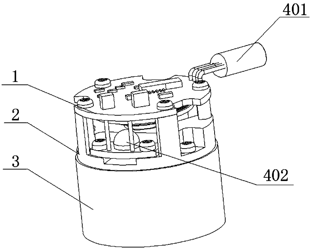
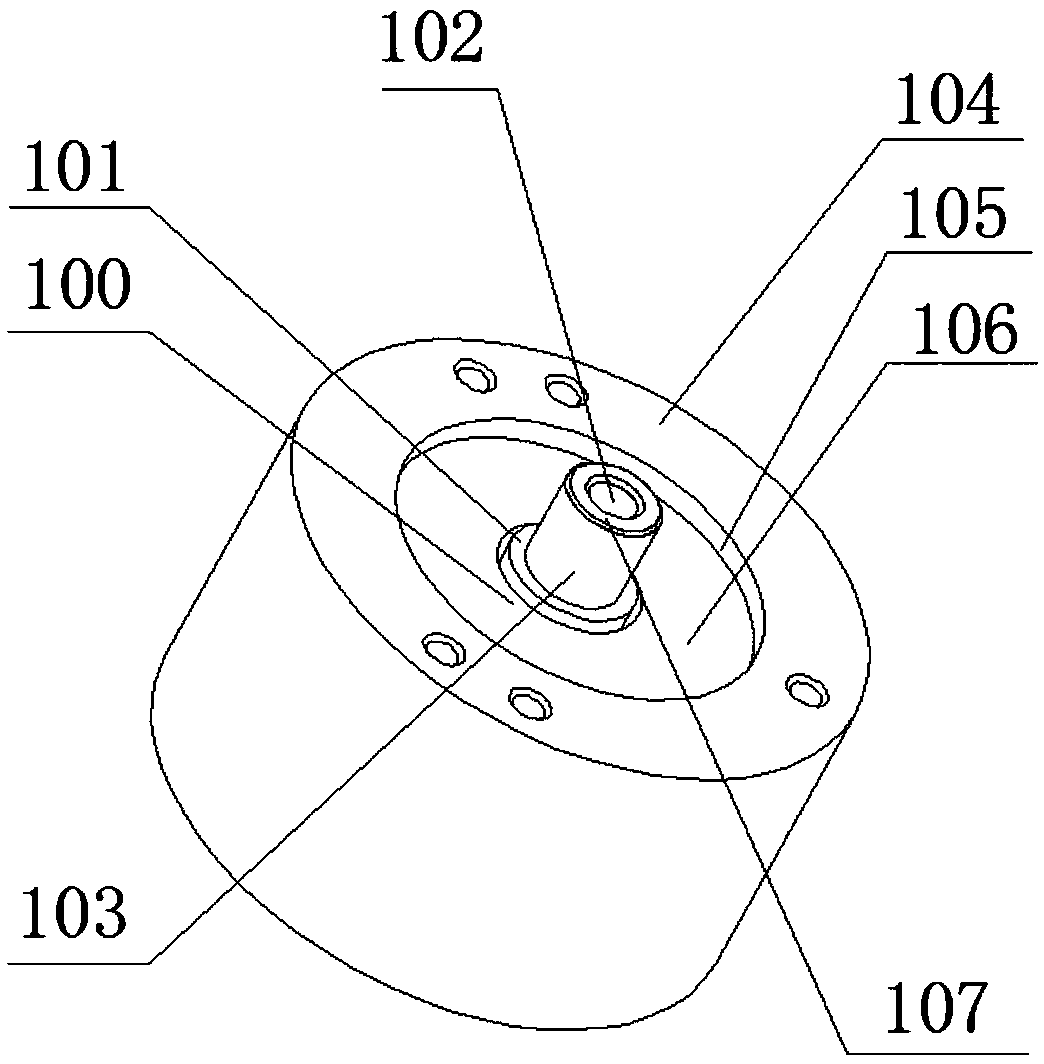
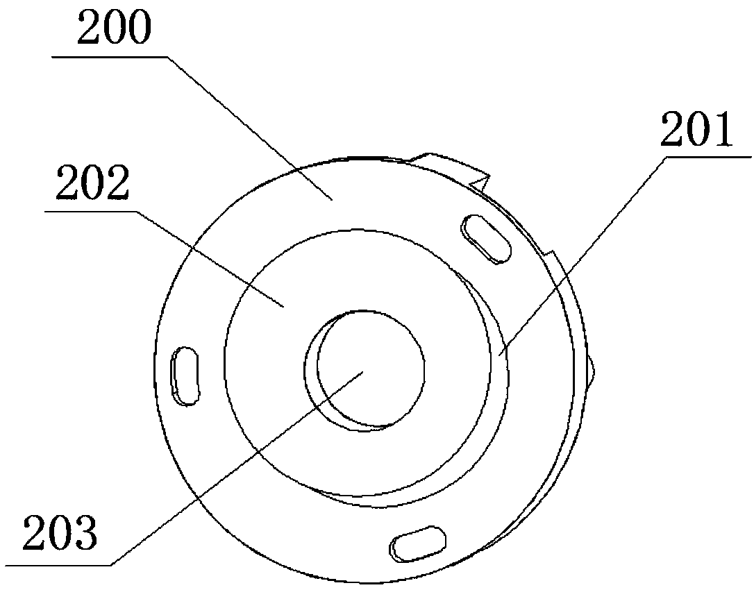
[0031] like figure 1 and Figure 5 The split encoder with the grating and the motor shaft integrated as shown includes a circuit board 1, a main body 2, a moving grating seat 300 and a motor 3. The circuit board 1 is fixed on the main body 2 by bolts, and the main body 2 is fixed on the motor 3 by bolts. on, such as figure 2 The shown motor 3 includes a first mounting surface 104, a second mounting surface 106, and a motor shaft 103, the first mounting surface 104 and the second mounting surface 106 are staggered to form a first circumferential surface 105, and the motor shaft 103 includes The shaft end face 107, the threaded hole 102 of the shaft center and the limit surface 101, such as image 3 The shown main body 2 includes a first mating surface 200, a second mating surface 202 and a central through hole 203, and the first mating surface 200 and the second mating surface 202 form a second circumferential surface 201 alternately, as shown in Figure 4 The moving gratin...

Embodiment 2

[0036] The difference between this embodiment and the first embodiment is that, if Figure 6 and Figure 7 The first mounting surface 104a of the motor is shown lower than the second mounting surface 106a, and the first mating surface 200a of the body is higher than the second mating surface 202a.

Embodiment 3

[0038] The difference between this embodiment and the first embodiment lies in that the second working surface 303 of the moving grating base 300 is in contact with the shaft end surface 107 of the motor 3 .


PUM


Abstract

The invention discloses a split encoder integrated with a grating and a motor shaft. The split encoder comprises a circuit board, a main body, a movable grating base and a motor, wherein the motor comprises a first mounting surface, a second mounting surface and the motor shaft, the first mounting surface and the second mounting surface are staggered to form a first circumferential surface, the motor shaft comprises a shaft end surface, a threaded hole in the axis and a limiting surface, the main body comprises a first fitting surface, a second fitting surface and a central through hole, the first fitting surface and the second fitting surface are staggered to form a second circumferential surface, a movable grating is mounted on the movable grating base, and the movable grating base is matched with the motor after passing through the central through hole of the main body. By adopting the bearingless mounting structure, the movable grating base is directly mounted on the motor shaft, and the motor shaft directly drives the movable grating base to rotate, thereby saving two bearings of the conventional encoder. The main body of the encoder is directly mounted onto the mounting planeof the motor, thereby saving a blade spring used for connecting the encoder main body and the motor for the traditional encoder.

Description

technical field [0001] The invention relates to the field of encoders, in particular to a split encoder in which gratings and motor shafts are integrated. Background technique [0002] According to the working principle of the photoelectric encoder, the encoder can be divided into two types: incremental type and absolute type. The incremental encoder converts the displacement into a periodic electrical signal, and then converts the electrical signal into a counting pulse, and uses the number of pulses to represent the magnitude of the displacement. Each position of the absolute encoder corresponds to a certain digital code, so its indication is only related to the start and end positions of the measurement, but has nothing to do with the middle process of the measurement. Now that the application of automation is becoming more and more extensive, the demand for encoders in the market is also increasing. [0003] Due to the increasing demand for encoders in the domestic mar...

Claims


Application Information

Patent Timeline
IPC IPC(8): G01D5/38
CPCG01D5/38
Inventor 倪国东
Owner CHANGCHUN RONGDE OPTICS
Why Eureka
Try Eureka