Wireless temperature-measurement monitoring device and method of high-voltage cable connector

A high-voltage cable, wireless temperature measurement technology, used in measurement devices, thermometers using electrical devices, and thermometers that are directly sensitive to heat and other problems to achieve the effect of solving energy consumption problems, reducing engineering workload and reliable communication

Inactive Publication Date: 2019-01-25
STATE GRID FUJIAN ELECTRIC POWER RES INST +2
View PDF9 Cites 5 Cited by
  • Summary
  • Abstract
  • Description
  • Claims
  • Application Information

AI Technical Summary

Problems solved by technology

[0009] 1. The temperature resolution is insufficient. The optical fiber temperature measurement recognizes the average temperature within a range of 1 meter, and the scanning time interval is 10s / km. It is impossible to find the temperature distribution on the cable joint and respond in time
[0010] 2. Large cost investment: For the construction environment, it is impossible to pull the optical fiber to the host, and there is a construction blind spot
[0012] 1. It is powered by batteries, generally used for 3 years, and there is a problem of service life
[0013] 2. Due to the low power consumption operation, the frequency of acquisition and communication is relatively low, and the real-time response is insufficient
[0015] Similar to optical fiber temperature measurement, the power and size of the host are relatively large. In the case of inconvenient wiring, the construction is very difficult. Because the resistance change obtained through metal deformation is irreversible, the applicable range is relatively small.

Method used


Image

  • Wireless temperature-measurement monitoring device and method of high-voltage cable connector
  • Wireless temperature-measurement monitoring device and method of high-voltage cable connector
  • Wireless temperature-measurement monitoring device and method of high-voltage cable connector

Examples


Embodiment Construction

[0040] The technical solution of the present invention will be specifically described below in conjunction with the accompanying drawings.

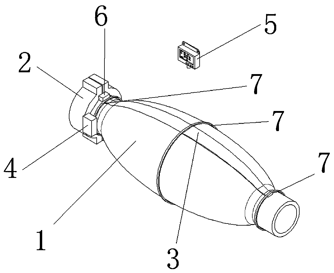
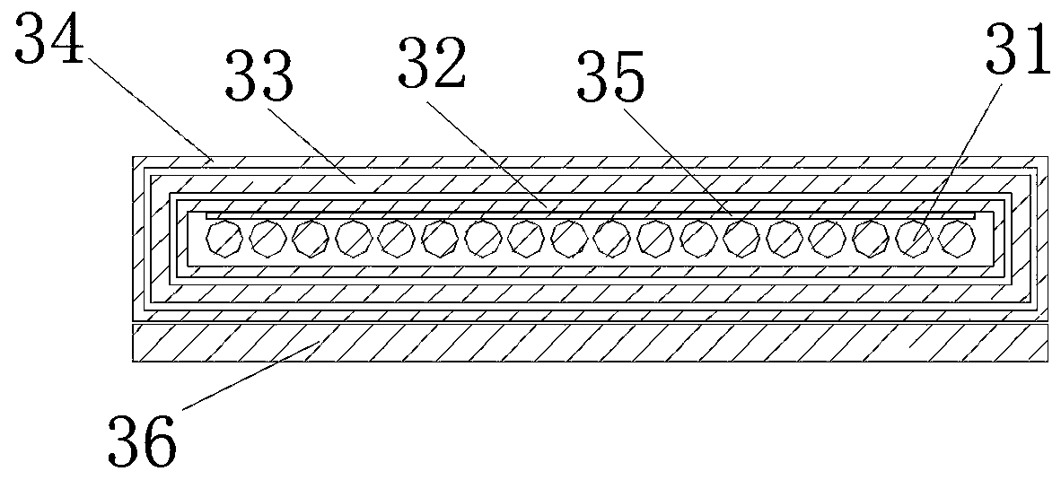
[0041] The invention provides a wireless temperature measurement and monitoring device for high-voltage cable joints, such as figure 1 As shown, it includes: an induction power-taking unit 2 arranged at one end of the high-voltage cable joint body 1, a strip-shaped temperature measurement unit 3 attached to the outer circumference of the high-voltage cable joint body and connected to the induction power-taking unit, and a high-voltage cable joint The acquisition and wireless communication unit 4 connected to the reaction power-taking unit and the strip temperature measurement unit at one end of the body, and the on-site centralized display unit 5 set at the high-voltage cable joint site and wirelessly matched with the acquisition and wireless communication unit. The strip temperature measurement unit includes a strip sensor and a waterpro...


PUM


Abstract

The invention relates to a wireless temperature-measurement monitoring device and method of a high-voltage cable connector. The device comprises an induction power taking unit, a strip-shaped temperature measurement unit, an acquisition and wireless communication unit and a site concentration display unit, wherein the site concentration display unit is wirelessly matched with the wireless communication unit. The method comprises the steps of monitoring a temperature of a high-voltage cable connector body by the strip-shaped temperature measurement unit, acquiring temperature data monitored bythe strip-shaped temperature measurement unit by the acquisition and wireless communication unit, and uploading the temperature data to the site concentration display unit; displaying the uploaded temperature data by the site concentration display unit, and uploading the temperature data to an upper computer of a monitoring center; and supplying power to the acquisition and wireless communicationunit by the induction power taking unit. Real-time acquisition of a multi-point high-frequency temperature is achieved under a high-electromagnetic environment, and the problem of low-power consumption and long-distance communication is solved by employing a Lora communication technology and an induction power taking technology.

Description

technical field [0001] The invention relates to a method based on a wireless temperature measurement and monitoring device for a high-voltage cable joint. Background technique [0002] Cable joints are a key component of cable power transmission. The process of cable joints includes insulation materials, stress control and crimping quality, and sealing and heat dissipation. It is easy to cause problems, so the failure rate of the cable head is high. According to statistics, cable head faults account for more than 80% of cable faults. [0003] Traditional high-voltage cable joint wireless temperature measurement and monitoring devices include the following: [0004] Distributed optical fiber temperature measurement: the temperature measurement optical fiber is used to wind the required cable joints as a whole, and the Roman reflection or Brillouin reflection device temperature change signal in the optical fiber is carried out through the host. It is characterized by long s...

Claims


Application Information

Patent Timeline
Patent Type & Authority Applications(China)
IPC IPC(8): G01K7/24G01K13/00G08C17/02G01K1/024
CPCG08C17/02G01K7/24G01K13/00
Inventor 黄友聪黄海鲲郑钟楠吴文斌王晓杰许军王宁燕谢文炳叶行汶方超颖陈亮娄坚鑫陈太
Owner STATE GRID FUJIAN ELECTRIC POWER RES INST
Why Eureka
Try Eureka