

Test circuit of infrared receiver
A technology of infrared receiving head and test circuit, which is applied in the direction of electrical connection test, etc., can solve the problems of low test efficiency, long time consumption, large error of manual reading value, etc., and achieve simple structure, convenient use, and improved automation Effect
- Summary
- Abstract
- Description
- Claims
- Application Information
AI Technical Summary
Problems solved by technology
Method used
Image

Examples
Embodiment 1
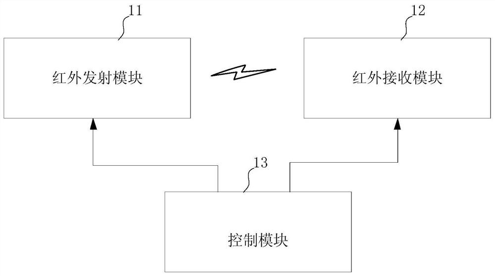
[0039] figure 1 Embodiment 1 of the present invention provides a block diagram of a test circuit of an infrared receiving head. The test circuit of the infrared receiving head in this embodiment is used to perform a compatibility test on the infrared receiving head during material replacement. The test circuit of the infrared receiving head in this embodiment includes an infrared emitting module 11 , an infrared receiving module 12 and a control module 13 .
[0040] The infrared emission module 11 is used for sending multiple infrared emission signals with different intensities in time division. In this embodiment, the infrared emitting module 11 includes at least one or more infrared emitters for emitting or external light. The operating current of the infrared emitter can be adjusted through a preset time interval, such as 10 seconds or 20 seconds, so that the infrared emitter sends out infrared emission signals of different intensities to simulate infrared rays with differ...
Embodiment 2
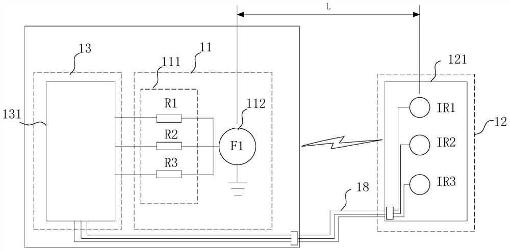
[0046] figure 2 A block diagram of a test circuit of an infrared receiving head provided in Embodiment 2 of the present invention. The test circuit of the infrared receiving head of this embodiment provides different resistances for controlling the intensity of the infrared transmission signal, so as to realize the detection of the infrared receiving head in the material Compatibility testing is performed during the replacement process. The test circuit of the infrared receiving head in this embodiment includes an infrared emitting module 11 , an infrared receiving module 12 and a control module 13 .
[0047] The infrared emitting module 11 includes a resistor module 111 and an infrared emitter 112 , the resistor module 111 is used to provide a variety of resistors with different resistance values, and one end of the resistor module 111 is connected to the infrared emitter 112 . In this embodiment, the resistor module 111 is a plurality of resistors with different resistance...
Embodiment 3
[0054] Figure 5 A block diagram of a test circuit of an infrared receiving head provided by Embodiment 3 of the present invention. The test circuit of the infrared receiving head in this embodiment provides a display device for displaying the compatibility test of the infrared receiving head during the material replacement process. result. The test circuit of the infrared receiving head in this embodiment includes an infrared emitting module 11 , an infrared receiving module 12 , a control module 13 and a display device 14 .
[0055] The infrared receiving module 12 includes a detection circuit board 121, and the detection circuit board 121 is used for detachably connecting at least one infrared receiving head to be tested. In this embodiment, the infrared receiving heads to be tested are three IR1-IR3.
[0056] The infrared emitting module 11 includes a resistance module 111 , an infrared emitter 112 and a switch module 113 .
[0057] In this embodiment, the resistance mod...
PUM
 Abstract
Description
Claims
Application Information