A support mechanism of a pressure transformer

A technology of transformer and support mechanism, which is applied in the direction of transformer/reactor installation/support/suspension, transformer/inductor cooling, etc. It can solve problems such as inconvenient installation, low work efficiency, and inconvenient adjustment of support height, etc., to achieve Easy to install, improve the anti-skid effect, and improve the effect of cooling and heat dissipation

Inactive Publication Date: 2019-01-25
常州耀洲众创空间有限公司
View PDF0 Cites 0 Cited by
  • Summary
  • Abstract
  • Description
  • Claims
  • Application Information

AI Technical Summary

Problems solved by technology

[0004] In order to solve the above technical problems, the present invention provides a new type of support structure for large-scale transformer coolers to solve the problems of inconvenient adjustment of support height, inconvenient installation and low work efficiency of the existing support structure of transformer coolers. question

Method used


Image

  • A support mechanism of a pressure transformer
  • A support mechanism of a pressure transformer
  • A support mechanism of a pressure transformer

Examples


Embodiment Construction

[0025] The present invention will be further described below in conjunction with accompanying drawing:

[0026] as attached figure 1 to attach Figure 4 shown

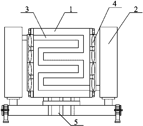
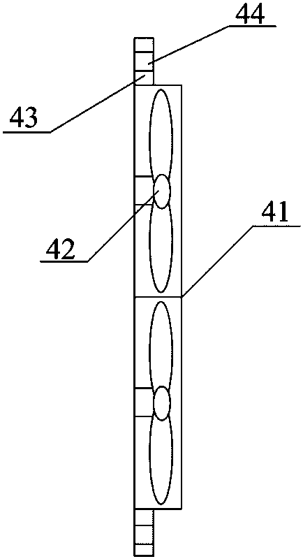
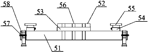
[0027] The present invention provides a support mechanism for a transformer, which includes a transformer 1, a water storage tank 2, a water pipe 3, an air blast cooling device 4 and a fixed base 5, and the transformer 1 is installed on the middle and upper part of the fixed base 5 The 4 bolts of the blast cooling device are installed on the left and right sides of the transformer device 1; the water pipes 3 are fixed on the front and rear sides of the transformer device 1; Both sides are installed on the top of the fixed base 5; the water pipe 3 is connected to the water storage tank 2; the fixed base 5 includes a base 51, a transformer bracket 52, a shock absorber 53, and a water storage tank bracket 54, Fixed plate 55, heat dissipation holes 56, supporting legs 57 and adjustment channels 58, the transformer brack...


PUM


Abstract

The invention provides a support mechanism of a pressure transformer, comprising a pressure transforming device, a water storage tank, a water pipe, an air blowing heat dissipation device and a fixedbase, wherein the pressure transforming device is installed in the middle and upper parts of the fixed base; Water pipes are fixed on the front and rear sides of the transformer; The water storage tank is located on the left and right sides of the pressure transformer and is installed on the upper part of the fixed base. The water pipe is connected with the water storage tank; The blast radiator is installed on the left and right sides of the pressure transformer through bolts; The blower and the heat dissipation hole of the invention are arranged so as to improve the cooling and heat dissipation effect of the transformer; The bolts of the blast radiating device are installed on the left and right sides of the pressure transformer, which is convenient to remove the blast radiating device in the pressure transformer and is convenient to install. The support leg is arranged and matched with the bayonet, which is favorable for conveniently lifting or lowering the height of the base; The rubber anti-skid pad supporting the lower part of the foot is arranged so as to improve the anti-skid effect.

Description

technical field [0001] The invention belongs to the technical field of supporting structure of a transformer cooler, and in particular relates to a novel supporting structure of a cooler of a large transformer device. Background technique [0002] Due to the weight of the large-scale transformer cooler, the lower part of the cooler needs to be supported by a transformer bracket. One end of the transformer bracket contacts the cooler and the other end contacts the foundation. The traditional support method is to determine the height of the support of the transformer device according to the design requirements. The height of the support of the transformer device is a fixed value. Due to the manufacturing tolerance of the components and the uneven foundation height, the support is not in place or the support is excessive, which cannot play the role of effective support. . [0003] However, the existing supporting structure of the transformer cooler still has the problems of in...

Claims


Application Information

Patent Timeline
Patent Type & Authority Applications(China)
IPC IPC(8): H01F27/06H01F27/08H01F27/16
CPCH01F27/06H01F27/08H01F27/16
Inventor 王兰云
Owner 常州耀洲众创空间有限公司
Why Eureka
Try Eureka